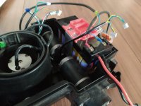
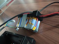
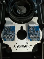
No problems Sascha but it's a work on progress and I will do a second one who will use rubber vibration damping to fix PCB's, because fixed directly on chassis, I don't think they will appreciate.Very cool.
Can you upload it here or on Thingiverse? I could use it too")
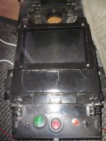
I thought about this also, but I'm also on thinking if it's really necessary if you use a tablet ?Now, if you can manage to design a replacement housing for the upper housing with the old number field, in which the 5" touch screen also fits, you are my friend
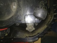
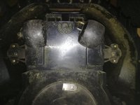
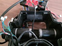
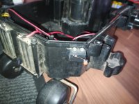
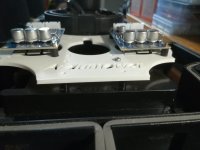
Well I haven't really bothered about those ones for now...I'm not sure, but maybe it's a good idea to remove the magnets on the right and left in the housing mounting, they could become a problem for the compass. There are also two at the top front of the case.
 for what is the compass used ? Bernard, to start which options should I take at first ? directly camera + HR-SR04 +... , perimeter cable ?
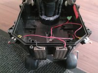
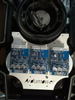
I'm also working on a bracket for 3 drivers but I have ordered new vibrations dampers ; I will add two stands at the front.
")