Teensy PCB Ardumower (T-Mow)

Ok, everything works for me now. The motors all turn, ticks per revolution are around 1200, but the shaft on the cutter motor is slightly crooked.
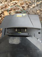
Raspberry Pi and TFT also work.
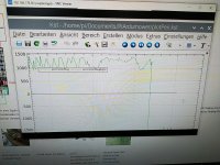
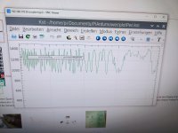
However, every now and then I get the error that the Teensy restarts because the loop takes too long. The mower is on my desk, I haven't found any errors yet.
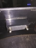
However, another IRF9540N is already broken. D4 and Q4 seem to be too close together.
The code can be adjusted in the driver.cpp:

Code:
void setBL500W(int pinDir, int pinPWM, int pinEnable, int speed) {
  if (speed < 0) {
    digitalWrite(pinDir, HIGH) ;
    //if (speed >= -4) speed = -4;
    analogWrite(pinPWM, ((byte)abs(speed)));
  } else {
    digitalWrite(pinDir, LOW) ;
    //if (speed <= 4) speed = 4;
    analogWrite(pinPWM, ((byte)abs(speed)));
  }
}
 
into setting IMU you need to Accel gyro initial calibration.
Maybe a bug if during calibration the teensy reboot : you need to increase the watchdog delay
 
I have upload the 1.1 version on Github with the correction for watchdog trig during imu calibration.
You need to use your own mower.h for correct motor setting
 
Thanks @Bernard , I have installed the new version, and it seems to be better.
But sometimes the IMU takes too long and then switches off, maybe I need to order a new one?

So, I was able to test the mower a bit today. I controlled it manually via the Pfod app. It worked pretty well, but a bit slow.
The connection of PfodApp and ESP is not stable when I am too close to it

Facing north also worked, but it wasn't north, it was east. But that's because the IMU is not aligned to the north.

The mower motor can also be switched on and off, but I had to set the current detection much higher.
It also takes a few tries before it starts up.

The loop receiver gets quite warm, is that normal?

I also rebuilt the charging station today, the original Ardumower Sender PCB fits into the charging station, I had it ready here and used it for testing.

I have a loop resistance of 5.5 ohms, which is apparently too low?

But I only have a 12 Ohm 50W resistor here, can I use that or do I have to get another one?

I think I'll leave out the camera, as I can't get a fan on the Raspberry any more, it's all too cramped.
 
But sometimes the IMU takes too long and then switches off, maybe I need to order a new one?
First check the soldering and if it's OK Test with other module.
I hope you have calibrate it with arduremote ?
Need Pitch and roll near 0 after calibration.

It worked pretty well, but a bit slow.
Here is the most important adjustment because you use BL motor and i never test this feature.
All ODO test need a good result.

Important value are the speed Max in PWM , speed Max in RPM , (speed odo Minimum in auto mode only)
First set the speed Max in RPM to maximum and Try to adjust in manual mode the speed Max in PWM .
When mower run at correct speed you can stop it and use command / OFF
Click on Calib motor ,normaly mower run at maxPWM for 3 or 4 meter.
This compute the ticks/sec and the RPM at maxPWM. maxRPM is now a new value.

Click on save setting

You can increase Speed ODO Minimum to avoid pause on movement in auto mode .

Facing north also worked, but it wasn't north
It's normal because you use IMU and not compass ,only compass can find north and it's never OK inside the mower.
IMU 0 is auto when you start the mower and drift over time.
Also reset to heading station in auto mode when start from station.

The loop receiver gets quite warm, is that normal?
I never see that ??

12 Ohm 50W resistor here
Use U=R*I adjusting the DC/DC sender voltage to 9V with R=12 Ohm result in 0.83 Amp in the loop and it's OK for small area .
What is the max perimeter Mag value near the wire ?

fan on the Raspberry any more
No problem for camera : Fan is only needed is you want to use AI detection but for only streaming you don't need it .
On PI you can easily add the temp of CPU in the toolbar.

Try to make a small video of the movement ,so i can tell you what setting to change.

And take a look at WIKI Setting motor part :
 
Yes IMU is calibrated with PfodApp.
Raspbery Console show:
Code:
18:37:21 Calibration address Stop = 650
18:37:21 Calibration address Start = 600
18:37:21 Save Calibration
18:37:21 THE NEW OFFSET ax: 699 ay: -3058 az: 1270 gx: 12 gy: -2 gz: 18
18:37:21  New reading ax: -3 ay: -3 az: 16378 gx: -1 gy: 1 gz: -1
18:37:21 FINISHED reading Value with new offset,If all is OK need to be close 0 exept the az close to 16384
18:37:17 Wait until accel 3 val are < 8 : 6 2 2 and Gyro 3 val are < 1 : 1 1 1
18:37:13 Wait until accel 3 val are < 8 : 5 2 1 and Gyro 3 val are < 1 : 1 1 2
18:37:09 Wait until accel 3 val are < 8 : 4 5 1 and Gyro 3 val are < 1 : 2 1 2
18:37:05 Wait until accel 3 val are < 8 : 2 5 0 and Gyro 3 val are < 1 : 2 1 3
18:37:01 Wait until accel 3 val are < 8 : 2 3 0 and Gyro 3 val are < 1 : 3 1 3
18:36:57 Wait until accel 3 val are < 8 : 2 2 2 and Gyro 3 val are < 1 : 3 1 4
18:36:53 Wait until accel 3 val are < 8 : 32 1 21 and Gyro 3 val are < 1 : 4 1 6
18:36:49 Wait until accel 3 val are < 8 : 231 151 178 and Gyro 3 val are < 1 : 5 2 7
18:36:45 Wait until accel 3 val are < 8 : 1232 2055 1429 and Gyro 3 val are < 1 : 7 3 9
18:36:41 Calculating offsets...
18:36:41 Reading ax: -6634 ay: 26374 az: 4960 gx: -7 gy: 3 gz: -10

The Perimeter Receiver is in the 3D Chassis from Laurent, it is not hot, but i can feel that is warm. I have to check again if I have done everything right.

I will do the perimeter test again tomorrow. I haven't adjusted anything on the DC/DC converter yet and can't tell how many volts it's set.
I got it like this and just wanted to test it quickly before it gets dark.
 
the DC/DC converter yet and can't tell how many volts it's set
Warning if the DC/DC is at max ,you send 24V to NANO or ESP32 and destroy them.
You need at max 12V and min 6/7 Volts at DC/DC output
 
Yes i know.
I have test the Receiver and now it seems to Work. One cable was loose. Look the Plot OK?
At the wave at the end I of the second Picture, i wanted to let the mower drive, but it says not in the perimeter area?
Perimeter cable about 10 meters long in the living room 3 meters apart.
 

Attachments

  • IMG_20220213_152141.jpg
    IMG_20220213_152141.jpg
    180.2 KB · Views: 19
  • IMG_20220213_152101.jpg
    IMG_20220213_152101.jpg
    1 MB · Views: 15
@LaurentS
The mower can not be charging in the Station with the Receiver Cover.
 

Attachments

  • IMG_20220213_155317.jpg
    IMG_20220213_155317.jpg
    823.3 KB · Views: 14
but it says not in the perimeter area?
Inside is ok when perimeter Mag is negative .
If it's not OK try to invert the 2 perimeter wire at the sender.

Something is not OK in the IMU or motor management ,certainly you need to increase the Speed Odo Minimum value.

Try to share a 2 minutes running and your var setting using Piardu / Console / List Var and Save to file.
Now into Documents/Piardumower/Log you can find a file named "date_time"_console.txt ,It's what i want to see.

Mower need to drive in straight line !!!!
 
I hope this is right file. Mower is switched on in the house
 

Attachments

  • Console.txt
    10.5 KB · Views: 5
Issue is in the motor torque, You use very low pwm value and firmware send for example pwm=70 to motor but the motor don't have enough torque to rotate when mower is on the floor.

So increase all the value.

Speed Odo Minimum = 50 is too low try with 80.
Speed max in pwm = 125 is also too low try with 180 or 200
Reduce Speed max in rpm if mower run too fast on the grass.
 
@LaurentS
The mower can not be charging in the Station with the Receiver Cover.
Is it because this part should come between contact plates ? I'm on Paris for two days, We will find the solution on wednesday; I also have an original charging station.
 

Attachments

  • Sans titre.jpg
    Sans titre.jpg
    253.1 KB · Views: 17
Yes it should center the Mower in the Station.
I could cut it off, but it's not great.
Have fun in Paris, if it's not work.
 
Yes it should center the Mower in the Station.
I could cut it off, but it's not great.
Have fun in Paris, if it's not work.
OK, we will find something, no problem. Thanks, it's not for work, it's for the familly and birthday celebration of one of the children; visit the Tour Eiffel, and Versailles Castle. :)
 
Hi Sascha, what I understood, this part is not for centering or guiding the mower as I thought previously but only to keep a distance when the charging plates come on contact with the charging points. I haven't mesured now, but it will be quiet easy to correct this thing. On mine, I will cut this part and stick a dampening rubber. As a first idea; I will watch this one more time tomorrow to be sure about my idea.
 
Last edited:
I have an idea.... well before this idea I will try with this.
 

Attachments

  • IMG_20220217_230642_resized_20220217_110708837.jpg
    IMG_20220217_230642_resized_20220217_110708837.jpg
    644.7 KB · Views: 14
Last edited:
Back
Top