Teensy PCB Ardumower (T-Mow)

Sascha

Administrator
Staff member
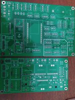
Momentan arbeiten ein paar Leute an einer Ardumower PCB, die auf einen Teensy 4.1 basiert.
Wer Lust und Interesse hat, kann sich auf der Github Seite darüber informieren.

Anschlüsse auf dem Board:
2 x Perimeter Empfänger
2x Sonar Sensoren
2x Bumper Sensor
1x Regensensor
1x GY-521 (3-Achsen Beschleunigungs-/ Lagesensor)
4x I2C Anschlüsse
1x PowerPCB Anschluss
2x Odometrie
2x Fahrmotor Anschlüsse
1x Mähmotor Anschluss

Was wird noch gebraucht?
Als Erstes wird natürlich die TeensyPCB benötigt, sie stellt das Gehirn des Mähroboters dar. An ihr werden alle benötigten Sensoren und Motoren angeschlossen. Um den T-Mower mit Strom zu versorgen, wird noch eine PowerPCB benötigt, welche in einem separaten Thread behandelt wird.
Mit den zwei PCB's habt ihr eigentlich schon eine gute Grundlage um mit dem Bau eures T-Mower Mähroboters zu beginnen.
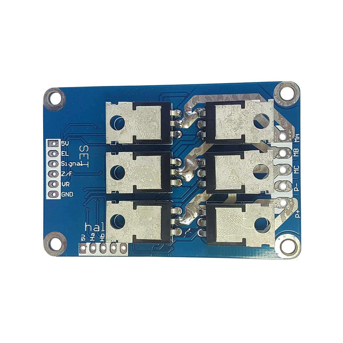
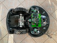
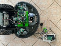
Es werden natürlich auch noch 2 Fahrmotoren und ein Mähmotor benötigt, die Motoren sollten möglichst Brushless Motoren sein und passende Brushless Motor Controller. Außerdem noch ein Akku und ein passendes Gehäuse.

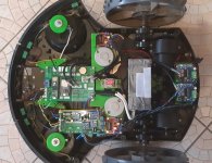
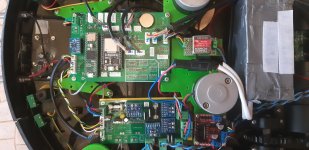
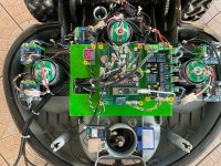
Hier ein paar Bilder aus einem umgebauten Tianchen TC-G158 und einem RL2000 mit 3 Mähmotoren.
 

Attachments

  • TeensyPCB.pdf
    179.2 KB · Views: 28
  • Mower.jpg
    Mower.jpg
    1.2 MB · Views: 50
  • PCB.jpg
    PCB.jpg
    705.2 KB · Views: 49
  • rl2000 teensy 2.jpg
    rl2000 teensy 2.jpg
    1 MB · Views: 54
  • rl2000 teensy 1.jpg
    rl2000 teensy 1.jpg
    1.1 MB · Views: 50
  • rl2000 teensy 3.jpg
    rl2000 teensy 3.jpg
    1 MB · Views: 51
Last edited:
First Teensy 4.1 Prototyp PCB has arrived.
 

Attachments

  • IMG_20210804_150021.jpg
    IMG_20210804_150021.jpg
    980 KB · Views: 61
What about the pin compatibility with the Ardumower PCB 1.3/1.4?
Plug&Play does not seem to work.
 
No the Teensy and the PCB are not Pin compatible.
The Azuritber Software need a rewrite, to Work with the Teensy.
 
Yes of course. But perhaps @Bernard can write itselfe about his Plan.
AS i know right, there a also more people interested in a Teensy PCB.
 
Last edited:
Oh thats a lot of Work.
Yes .
On PCB1.3 and 1.4 motor driver are totaly integrate.They are OK for small motor and the total cost is near 200 Eur ,so more expansive than a commercial mower PCB also unfortunately not something DIY like PCB1.2. If you burn something it's really complex to work on smd part.
So They are build for Ardumower Platform and work perfectly for that.

But i rebuild old Mower so my goal was to use a PCB that can manage the motor driver that you want with possible DIY and at low cost.

The result is no SMD but directly use best existing parts (The one i know) like CPU-> TEENSY /Communication-> ESP32 / IMU-> MPU6050 /Sense mesurement->INA226 etc..

To avoid mixte low and high voltage 2 PCB are build .
The Power one manage Battery and charge and measure voltage and current on different output line .
The Main one compute everything and can be a teensy or Raspberry or Due .

PCB are Build but never powered so as you can imagine stay a lot of work.
 
Hello Bernard,
I'm interested in the power PCB to monitor and control battery and charging. Would be great if you share some information about it.

BR Patrick
 
You have the kicad file in azuritber Github repo into PCB.
It's PowerPCB V1.06 and teensy pcb

BT1 : Charger connector
J2 Battery (24V 7S li/ion)
J3 ARU
J11 / J12 24V out to power some DC/DC voltage regulator to power the main PCB , but no sense mesurement.
J4 J6 J7 J9 J10 24V out to power motor with I2C sense mesurement using INA226 U2 to U6
J8 Button or 3.3V on J1 -> PinBatterySwitch is use to send or stop battery voltage on the OUT connector.
3.3V on J1 -> PinChargeEnable is used to link the charger and battery and start charge process.. U1 is the I2C sense charging feedback.

So the simple working mode is to shunt J3 , put batterty on J2 (nothing on output) Press the J8 button --> so 24V is present on J11--> DC/DC to 3.3V or 5V for main PCB and a 3.3V from the main PCB (DUE/Teensy etc..) is back to J1 -> PinBatterySwitch and OUT stay on so you can release J8.

Main PCB can POWER OFF by release the 3.3V on J1 -> PinBatterySwitch

2 I2C line are used because only 3 INA226 can be connected on the same bus
 

Attachments

  • charge_pcb.pdf
    56.5 KB · Views: 32
Test of Power PCB V1.06 is OK with ESP8266 3.3V module.
R10 and R11 i use 4.7K . D3 is not mount.


TESTED:
Button start and board keep powered after 3.3V on pinbatswitch.
Battery charging start and stop using 3.3V on pincharge.
Reading I2C charge Voltage and current .
Power off everything when release 3.3V on pinbatteryswitch.

NOT YET TESTED the motor sense I2C feedback..


Test of Teensy PCB is not OK on the voltage divider and i see that it's the same error on the SIMPLE DUE PCB (But it's work in my case).
Need a small solder workarround.
Be carreful to not power Teensy with USB and Battery at same time without cutting the correct trace.

For software AZURITBER :
RTC and Timer are OK 3V bat keep date time after power OFF.
Bumper is OK
Rain is OK
Start button is OK
ODOMETRY OK
Comminucation with ESP and arduremote working OK.
IMU is OK.

TODO and not the easier part:
Check the ADC Manager (using or not DMA ,i take a look at @Sascha code for this).
Add the perimeter reading.

Set the BTS7960 and L298N driver to work
:oops:

And vacation (y)

Code is on my git redo under a new TEENSY part.
 
Sound good :)

Picture?

Test of Teensy PCB is not OK on the voltage divider and i see that it's the same error on the SIMPLE DUE PCB (But it's work in my case).
Need a small solder workarround.
Oh ok, what is wrong?

TODO and not the easier part:
Check the ADC Manager (using or not DMA ,i take a look at @Sascha code for this).
Add the perimeter reading.
You mean @Fürst Ruprecht ?

Set the BTS7960 and L298N driver to work
And Brushless Driver? 😇

And vacation
My holiday has just ended and of course I have managed almost nothing (children have vacation).
I wish you a nice holiday
 
Everything is working on 1 hour test .
Code rebuilding was not easy but the teensy is really more powerful than DUE.

Now i need to move all the electronics to another RL2000 robomow .

Not finish is the sonar management and maybe some test on BL motor , but i need first to have one working using a ESP8266 or ESP32 3.3V module.

On the PCB no particular surprise except the resistor for voltage divisor.
Here how to solder the resistor:

20210918_125754.jpg20210918_125812.jpg
 
Ok thanks for your Info.
Did you now have Brushless Motors for tests?
Really good work.
 
Did you now have Brushless Motors for tests?
I have 2 overboard BL motor and one BDUAV 5065-270KV (for mowing)
But i don't understand .
I try to use this kind of driver:

On overboard it did it rotate for 10 minutes and now i can't make it rotate again
On BDUAV the motor rotate 5 second with a lot of noise and Driver burn completly :mad:

The paddy projet is very good and when i finish the RL2000 teensy i try to build something with teensy and overboard wheel.

But it's take time :ROFLMAO::ROFLMAO::ROFLMAO:
 
Yes i have the same Drivers, they seems to work for me. But only test with small Code.
As i understand it right, the Teensy PCB need only a USART Connector to Communicate with the Hover Board PCB.
I first need a Chassis with more space in it, the Matrix Chassis is annoying :mad:

Yes time is a big factor, I am building a Corexy printer and a second one arrived today, lots of work
 
the Teensy PCB need only a USART Connector to Communicate with the Hover Board PCB.
Yes it's also what i understood but in my case the overboard PCB is different and it use 2 PCB ,one for each wheel , paddy send me a link to the hack firmware but not yet tested and i hope that the USART and bl motor react time is correct.
 
Hello Bernard,
Is Ardumower_teensy_pro up to date (Ardumower.pdf)?
I think the pins D18,D19=SDA,SCL and the PINs D20,D21=TX5,RX5 are swapped in your schematic.
Do you have a complete circuit diagram of the Teensy/esp32 board? I can not find it at github.
Do you sell boards? I would be interested, but would like to check first whether I can operate 4WD + steering with it.

Gruß Fürst Ruprecht
 
Is Ardumower_teensy_pro up to date (Ardumower.pdf)?
:ROFLMAO: :ROFLMAO: Sorry like you can see i use the Due project as template !
It's change.
D18,D19=SDA,SCL and the PINs D20,D21=TX5,RX5
It's OK for me not swapped (Why did you say that ?)
Do you have a complete circuit diagram of the Teensy/esp32 board?
Do you sell boards? I would be interested, but would like to check first whether I
I have 1 set left , but you need to check what you need as output to manage the 4 motors.
I build actualy the RL2000 teensy ,so i can tell you how many pins are nedded for 4 drive motor and 1 mow motor.
Sense feedback use I2C , so no problem.
 
Back
Top