Yesterday I tested the espressif sketch. Unfortunately, I have no idea how to swap the I2C pins there. so I didn't get any data either.
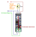
I have an idea, could it be that the I2C change in the Wifi transmitter sketch had no effect on the hardware!? no matter how I swap the I2C pins in the sketch, the oled display always works!? that shouldn't be the case!? I found 3 devices with the I2C scanner sketch. 2 x Ina226 and the display. But only when I have swapped the sda and scl pins on the display cable do I find that. If I now load the wifi transmitter Sketch on it, I have to swap the 2 pins on the display cable back again, otherwise there is no picture!? that almost sounds as if the assignment in the wifi sketch had no effect!?
just an idea...
So ich hatte gestern den espressif sketch mal getestet. Nur leider habe ich dort keine ahnung, wie ich die I2C pins tauschen kann. also habe ich auch keine daten bekommen.
Ich habe da so eine idee, könnte es sein das die I2C änderung im Wifi Sender sketch auf die Hardware keinen einfluss hatt!? egal wie ich die I2C pins im sketch Tausche, das oled Display geht immer!? das dürfte doch gar nicht sein!?
Ich habe mit dem I2C scanner sketch, 3 Geräte gefunden. 2 x Ina226 und das display. Aber erst nur wenn ich am displaykabel die sda und scl pins getauscht habe finde ich das.
Lade ich nun den wifi sender sketch drauf muss ich die 2 pins am display kabel wieder zurücktauschen sonst gibts kein bild!? das klingt fast so als wenn die zuweisung im wifi sketch keine auswirkung hatt!? nur so eine Idee...

")
")