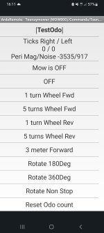
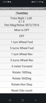
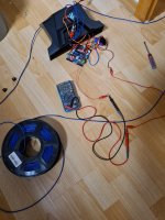
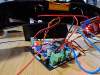
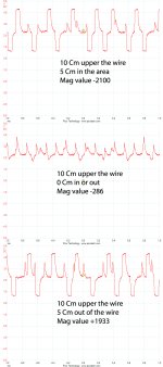
Start Probleme

There is 1.62v on teensy pin 23 and 2.4v com from lm386
It's OK , so the resistor are correctly soldered.
But the result is very strange.
Change the resistor on the perimeter wire to have more than 600ma in the sender sense and Test with new LM386 and coil from shop.
 
Da habe ich 35 ohm zwischen den beiden!?
Wenn ich mich nicht irre, müssten es 10kohm sein... Hast du mal am Poti in die andere Richtung gedreht?
Gegen den Uhrzeigersinn muss er gedreht werden, also links herum!
 
Last edited:
Wenn ich mich nicht irre, müssten es 10kohm sein... Hast du mal am Poti in die andere Richtung gedreht?
Gegen den Uhrzeigersinn muss er gedreht werden, also links herum!
Ja ist ganz nach links Anschlag, das sollte, volle Leistung sein! Na ich müsste heut ein neues Modul bekommen da werd ich mal sehen ob es anders ist.
 
Hallo,
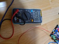
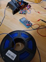
so also der neue Empfänger und die spule bringt schon mal andere und bessere werte. Aber ich bekomme keine richtigen mA aus meinem Sender herausgekizzelt. Es sind nach wie vor nur 0.97 mA verbrauch bei 100m Draht, vom Sender zum Motortreiber für den Draht. Das ist doch viel zu wenig oder? Ist das evtl. Ungünstig das der draht zum großen teil noch auf Rolle ist!?

Hello, so the new receiver and the coil bring different and better values. But I'm not getting any real mA out of my transmitter. It is still only 0.97 mA consumption for 100m of wire, from the transmitter to the motor driver for the wire. That's way too little, isn't it? Is it possibly unfavorable that most of the wire is still on a roll!?
 

Attachments

  • Screenshot_20230723_161221_ArduRemote.jpg
    Screenshot_20230723_161221_ArduRemote.jpg
    596.3 KB · Views: 3
  • Screenshot_20230723_161155_ArduRemote.jpg
    Screenshot_20230723_161155_ArduRemote.jpg
    523.7 KB · Views: 2
  • Screenshot_20230723_161206_ArduRemote.jpg
    Screenshot_20230723_161206_ArduRemote.jpg
    526.9 KB · Views: 2
  • 20230723_184221.jpg
    20230723_184221.jpg
    1.1 MB · Views: 2
  • 20230723_184240.jpg
    20230723_184240.jpg
    764.2 KB · Views: 3
  • 20230723_184339.jpg
    20230723_184339.jpg
    719.4 KB · Views: 4
  • 20230723_184259.jpg
    20230723_184259.jpg
    841.8 KB · Views: 4
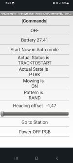
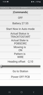
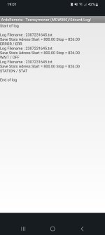
Heut auch wieder einen kleinen testaufbau im Garten gemacht. mit der Funktion "Lane" fuhr er eigentl. Eine Weile schön in dem Bereich abgespeckten bereich herum. Aber bei "Wire" zum beispiel, hört er relativ schnell auf mit folgender Meldung POBSCIRC!? BEI Rand mit PTRK!?
Gibt es da eine Anleitung woe mann da am besten herangeht? Er hört meistens auf das der buzzer schellt und ich habe keine Ahnung was los ist!?

Today also made a small test setup in the garden. with the function "Lane" he actually drove. A while nice in the area slimmed down area around. But with "Wire" for example, it stops relatively quickly with the following message POBSCIRC!? AT edge with PTRK!? Is there a guide on how to best approach it? He usually listens to the buzzer ringing and I have no idea what's going on!?
 

Attachments

  • Screenshot_20230723_152201_ArduRemote.jpg
    Screenshot_20230723_152201_ArduRemote.jpg
    499.1 KB · Views: 3
  • Screenshot_20230723_152039_ArduRemote.jpg
    Screenshot_20230723_152039_ArduRemote.jpg
    506.2 KB · Views: 4
  • Screenshot_20230723_190127_ArduRemote.jpg
    Screenshot_20230723_190127_ArduRemote.jpg
    443.2 KB · Views: 3
  • Screenshot_20230723_190218_ArduRemote.jpg
    Screenshot_20230723_190218_ArduRemote.jpg
    819.2 KB · Views: 6
Mit dem Multimeter habe ich nie nachgemessen. Ist ja auch eher eine Rechteckspannung. Weiss nicht ob du da vielleicht doch im Wechselstrom Bereich messen musst? Was sagt denn das INA Modul?

POBSIRC bedeutet dass ein Hinderniss im Weg war und dass möchte der Mäher dann umfahren. Hinderniss kann z.B. durch den Bumper erkannt werden, aber auch durch den Motorstrom. Die Ausgabe der Console sollte da weitere Infos liefern.

PTRK bedeutet dass der Mäher dem Perimeterdraht folgt...? Das sollte nur bei start aus der Station heraus kommen, denn nach dem Ausparken fährt der Mäher eine definierte Strecke auf dem Perimeterdraht und fängt dann an zu mähen.

I never checked with the multimeter. It's a square wave. Don't know if you might have to measure in the AC range? How much mA the INA module say? POBSIRC means that there was an obstacle in the way and the mower wants to avoid it. Obstacles can be detected e.g. by the bumper, but also by the motor current. The console output should provide more information. PTRK means the mower follows the perimeter wire...? This should only happen when you start out of the station, because after the Stationstart the mower drives a defined distance on the perimeter wire and then starts mowing.
 
Hast du mal versucht die 2. Schleife in Betrieb zu nehmen? Vielleicht liegt ein defekt am Ausgang der A-Schleife vor?

Have you tried to activate the 2nd loop? Perhaps there is a defect at the output of the first loop?
 
Mit dem Multimeter habe ich nie nachgemessen. Ist ja auch eher eine Rechteckspannung. Weiss nicht ob du da vielleicht doch im Wechselstrom Bereich messen musst? Was sagt denn das INA Modul?

POBSIRC bedeutet dass ein Hinderniss im Weg war und dass möchte der Mäher dann umfahren. Hinderniss kann z.B. durch den Bumper erkannt werden, aber auch durch den Motorstrom. Die Ausgabe der Console sollte da weitere Infos liefern.

PTRK bedeutet dass der Mäher dem Perimeterdraht folgt...? Das sollte nur bei start aus der Station heraus kommen, denn nach dem Ausparken fährt der Mäher eine definierte Strecke auf dem Perimeterdraht und fängt dann an zu mähen.

I never checked with the multimeter. It's a square wave. Don't know if you might have to measure in the AC range? How much mA the INA module say? POBSIRC means that there was an obstacle in the way and the mower wants to avoid it. Obstacles can be detected e.g. by the bumper, but also by the motor current. The console output should provide more information. PTRK means the mower follows the perimeter wire...? This should only happen when you start out of the station, because after the Stationstart the mower drives a defined distance on the perimeter wire and then starts mowing.
Vielen Dank Stefan, wo kann mann das denn nachlesen!? Ich sehe immer irgendwelche meldung und Abkürzungen, kann aber nichts damit anfangen.
Na gemessen habe ich das was der ina theoretisch auch misst den Gleichstrom der zum Motortreiber geht. Das müsste ja noch ein ganz normaler Stromkreis sein.!?
 
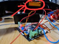
Oh yes, here is the little Monster 12ohm 50w.
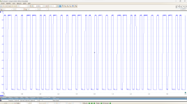
If you have a scope :
here what you need to see at the output of the L298N whithout the resistor and wire: (+ or -9V) with the sigcode
Capture d'écran 2023-07-23 202106.png
And at the receiver. Mag value are for arduino DUE ,for teensy it's near 10 or 15000
receiver scope.jpg
 
If you have a scope :
here what you need to see at the output of the L298N whithout the resistor and wire: (+ or -9V) with the sigcode
View attachment 992
And at the receiver. Mag value are for arduino DUE ,for teensy it's near 10 or 15000
View attachment 993
No, unfortunately I haven't, but the driver should send 9v to the line? With me it only sends 5v to the wire at 10V input!?
I will try the lm!

Nein habe ich leider nicht, aber der treiber sollte 9v auf die Leitung schicken? Bei mir schickt er nur 5v auf den Draht bei 10V eingang!?
 
No, unfortunately I haven't, but the driver should send 9v to the line? With me it only sends 5v to the wire at 10V input!?
Your multimeter can't mesure the high frequency signal and the 5V result is certainly a rounded value of the frequency (+10,-10V)
In all case your multimeter into Sense mode is perfect to see what's append in the wire and you need to see more than 0.98mA certainly 750mA

Can you share the code you use on the sender ?
 
Vielen Dank Stefan, wo kann mann das denn nachlesen!? Ich sehe immer irgendwelche meldung und Abkürzungen, kann aber nichts damit anfangen.
Na gemessen habe ich das was der ina theoretisch auch misst den Gleichstrom der zum Motortreiber geht. Das müsste ja noch ein ganz normaler Stromkreis sein.!?

Es ist ein Wechselstrom Schaltkreis mit unregelmäßiger Rechteckspannung. Das geht in Richtung Frequenztechnik und das ist ziemlich kompliziert. Die Wirkweise der Ardumower - Perimeterschleife kann man gut nachlesen.

Die Abkürzungen leiten sich aus dem englischen ab. Und auch aus der Erfahrung 😉
 
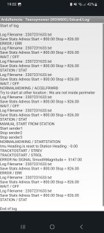
On the console you can see the STATUS / STATE of the mower over time and some text on what's append .

For example in your console:

Mower is in station and wait (no charging) --> STATION / STAT
You click on start so:
manual start from station
start sender1 ( a wifi command is send by the mower to sender
stop sender2
stop sender3
NORMALMOWING/STARTSTATION -->STATE_START_FROM_STATION, //when mower is station and a start command is receive need to start again IMU ,perimeter signal etc.... and wait 3s
IMU heading is reset
station reverse (mower reverse for x meter)
station rol (mower rol for y degre)
Now the mower check if the sender work and try to read the signal but fail because detect mower is outside.( Mag is >0 and need a negative value)
ERROR No SIGNAL SmoothMagnitude =5147.00

SO try to put mower inside the perimeter and check if Mag left is negative,: If it's positive invert the 2 perimeter wire at the output of the sender.


STATUS in full text
Code:
WAIT
NORMAL_MOWING
SPIRALE_MOWING
BACK_TO_STATION
TRACK_TO_START
MANUAL
REMOTE
IN_ERROR
IN_STATION
TESTING
WAITSIG2
WIRE_MOWING
Status in abreviation
Code:
"WAIT"
"NORMALMOWING",
"SPIRALEMOWING",
"BACKTOSTATION",
"TRACKTOSTART",
"MANUAL"
"REMOTE",
"ERROR",
"STATION"
"TESTING",
"SIGWAIT" ,
"WIREMOWING"
                            };

and STATE in full text
Code:
STATE_OFF,          // off
  STATE_REMOTE,       // model remote control (R/C)
  STATE_FORWARD,      // drive forward
  STATE_ROLL,         // drive roll right/left
  STATE_REVERSE,      // drive reverse
  STATE_CIRCLE,       // drive circle
  STATE_ERROR,        // error
  STATE_PERI_FIND,    // perimeter find
  STATE_PERI_TRACK,   // perimeter track
  STATE_PERI_ROLL,    // perimeter roll
  STATE_PERI_REV,     // perimeter reverse
  STATE_STATION,       // in station
  STATE_STATION_CHARGING,       // in station charging
  STATE_STATION_CHECK, //checks if station is present
  STATE_STATION_REV,   // charge reverse

  STATE_STATION_ROLL,  // charge roll
  STATE_STATION_FORW,  // charge forward
  STATE_MANUAL,       // manual navigation
  STATE_ROLL_WAIT,    // drive roll right/left
  STATE_PERI_OUT_FORW, // outside perimeter forward driving without checkPerimeterBoundary()
  STATE_PERI_OUT_REV,   // outside perimeter reverse driving without checkPerimeterBoundary()
  STATE_PERI_OUT_ROLL,   // outside perimeter rolling driving without checkPerimeterBoundary()
  STATE_PERI_OBSTACLE_REV,     // perimeter reverse when hit obstacle
  STATE_PERI_OBSTACLE_ROLL,     // perimeter roll when hit obstacle
  STATE_PERI_OBSTACLE_FORW,     // perimeter forward after roll obstacle
  STATE_PERI_OBSTACLE_AVOID,     // perimeter circle to avoid obstacle
  STATE_NEXT_LANE_FORW, // use after roll to reach the next lane
  STATE_PERI_OUT_STOP, // use to stop slowly on perimeter before reverse
  STATE_PERI_OUT_LANE_ROLL1,// roll always to 135 deg with brake
  STATE_PERI_OUT_LANE_ROLL2,// roll one wheel to put in straight line with brake

  STATE_PERI_OUT_ROLL_TOINSIDE,   // outside perimeter rolling driving without checkPerimeterBoundary()
  STATE_WAIT_AND_REPEAT, // use to repeat a state until something change for example find again perimeter by rolling
  STATE_FORWARD_ODO,      // drive forward odometry control straigh line and not speed in rpm
  STATE_TEST_COMPASS,    // drive roll right/left FOR A SPECIFIQUE ANGLE
  STATE_PERI_OUT_ROLL_TOTRACK,   // outside perimeter rolling driving without checkPerimeterBoundary()
  STATE_PERI_STOP_TOTRACK, // brake when reach the wire before roll to start tracking
  STATE_AUTO_CALIBRATE,  //wait until the drift is stopped and adapt the gyro and compass
  STATE_ROLL_TO_FIND_YAW, //try to find the compass yaw = yawheading
  STATE_TEST_MOTOR, //use to test the odometry motor
  STATE_STOP_TO_FIND_YAW, // brake before roll to find yaw
  STATE_STOP_ON_BUMPER,   //stop immediatly on bumper
  STATE_STOP_CALIBRATE,   //don't move during 15 sec for DMP autocalibration.
  STATE_SONAR_TRIG,      // when sonar detect obstacle brake gently before reverse
  STATE_STOP_BEFORE_SPIRALE,     //brake gently before start the spirale
  STATE_MOW_SPIRALE,      //mowing a CIRCLE ARC of increaseing diameter to make the spirale

  STATE_ROTATE_RIGHT_360,  // simple mowing rotation at the beginning of the spirale
  STATE_NEXT_SPIRE,  //go to next CIRCLE ARC in SPIRALE MODE
  STATE_ESCAPE_LANE,  //grass is high need to reduce the lenght of the lane
  STATE_PERI_STOP_TOROLL,  //use when timer start the mowing or when tracking and find RFID need to stop before roll
  STATE_ROLL_TONEXTTAG,  //use when tracking and find RFID tag the mower roll to new heading
  STATE_PERI_STOP_TO_NEWAREA,  //use when tracking and find RFID need to stop before roll to leave the area
  STATE_ROLL1_TO_NEWAREA,  //use when tracking and find RFID need to roll to leave the area
  STATE_DRIVE1_TO_NEWAREA,  //use when tracking and find RFID need to drive to leave the area
  STATE_ROLL2_TO_NEWAREA,  //use when tracking and find RFID need to roll to leave the area
  STATE_DRIVE2_TO_NEWAREA,  //use when tracking and find RFID need to drive to leave the area

  STATE_WAIT_FOR_SIG2,  //use when the area 2 wait until sender send the signal
  STATE_STOP_TO_NEWAREA,  //use to stop the mower in straight line after long distance moving with ODO and IMU
  STATE_PERI_OUT_STOP_ROLL_TOTRACK, // after the mower rool to track we need to stop the right motor because it's reverse and the track is forward
  STATE_PERI_STOP_TO_FAST_START,  // after the mower find a tag for find a new start entry point
  STATE_CALIB_MOTOR_SPEED,  // we need to know how may ticks the motor can do in 1 ms to compute the maxododuration
  STATE_ACCEL_FRWRD, // when start from calib or off need to accel before motorodo
  STATE_ENDLANE_STOP, //when mower is at the end of the lane avoid to reverse before roll
  STATE_START_FROM_STATION, //when mower is station and a start command is receive need to start again IMU ,perimeter signal etc....
  STATE_BUMPER_REV,   // rev when bumper is hit
  STATE_WAIT_COVER,  // on start wait until user close the security cover

State in abreviation:
Code:
"OFF"
"RC"
"FORW"
"ROLL"
"REV",
"CIRC",
"ERR",
"PFND",
"PTRK",
"PROL",
"PREV",
"STAT",
"CHARG",
"STCHK",
"STREV",
"STROL",
"STFOR",
"MANU",
"ROLW",
"POUTFOR",
"POUTREV",
"POUTROLL",
"POBSREV",
"POBSROLL",
"POBSFRWD",
"POBSCIRC",
"NEXTLANE",
"POUTSTOP",
"LANEROL1",
"LANEROL2",
"ROLLTOIN",
"WAITREPEAT",
"FRWODO",
"TESTCOMPAS",
"ROLLTOTRACK",
"STOPTOTRACK",
"AUTOCALIB",
"ROLLTOFINDYAW",
"TESTMOTOR",
"FINDYAWSTOP",
"STOPONBUMPER",
"STOPCALIB",
"SONARTRIG",
"STOPSPIRAL",
"MOWSPIRAL",
"ROT360",
"NEXTSPIRE",
"ESCAPLANE",
"TRACKSTOP",
"ROLLTOTAG",
"STOPTONEWAREA",
"ROLL1TONEWAREA",
"DRIVE1TONEWAREA",
"ROLL2TONEWAREA",
"DRIVE2TONEWAREA",
"WAITSIG2",
"STOPTONEWAREA",
"ROLLSTOPTOTRACK",
"STOPTOFASTSTART",
"CALIBMOTORSPEED",
"ACCELFRWRD",
"ENDLANE",
"STARTSTATION",
"BUMPREV",
"WAITCOVER"
                           };
 
On the console you can see the STATUS / STATE of the mower over time and some text on what's append .

For example in your console:

Mower is in station and wait (no charging) --> STATION / STAT
You click on start so:
manual start from station
start sender1 ( a wifi command is send by the mower to sender
stop sender2
stop sender3
NORMALMOWING/STARTSTATION -->STATE_START_FROM_STATION, //when mower is station and a start command is receive need to start again IMU ,perimeter signal etc.... and wait 3s
IMU heading is reset
station reverse (mower reverse for x meter)
station rol (mower rol for y degre)
Now the mower check if the sender work and try to read the signal but fail because detect mower is outside.( Mag is >0 and need a negative value)
ERROR No SIGNAL SmoothMagnitude =5147.00

SO try to put mower inside the perimeter and check if Mag left is negative,: If it's positive invert the 2 perimeter wire at the output of the sender.


STATUS in full text
Code:
WAIT
NORMAL_MOWING
SPIRALE_MOWING
BACK_TO_STATION
TRACK_TO_START
MANUAL
REMOTE
IN_ERROR
IN_STATION
TESTING
WAITSIG2
WIRE_MOWING
Status in abreviation
Code:
"WAIT"
"NORMALMOWING",
"SPIRALEMOWING",
"BACKTOSTATION",
"TRACKTOSTART",
"MANUAL"
"REMOTE",
"ERROR",
"STATION"
"TESTING",
"SIGWAIT" ,
"WIREMOWING"
                            };

and STATE in full text
Code:
STATE_OFF,          // off
  STATE_REMOTE,       // model remote control (R/C)
  STATE_FORWARD,      // drive forward
  STATE_ROLL,         // drive roll right/left
  STATE_REVERSE,      // drive reverse
  STATE_CIRCLE,       // drive circle
  STATE_ERROR,        // error
  STATE_PERI_FIND,    // perimeter find
  STATE_PERI_TRACK,   // perimeter track
  STATE_PERI_ROLL,    // perimeter roll
  STATE_PERI_REV,     // perimeter reverse
  STATE_STATION,       // in station
  STATE_STATION_CHARGING,       // in station charging
  STATE_STATION_CHECK, //checks if station is present
  STATE_STATION_REV,   // charge reverse

  STATE_STATION_ROLL,  // charge roll
  STATE_STATION_FORW,  // charge forward
  STATE_MANUAL,       // manual navigation
  STATE_ROLL_WAIT,    // drive roll right/left
  STATE_PERI_OUT_FORW, // outside perimeter forward driving without checkPerimeterBoundary()
  STATE_PERI_OUT_REV,   // outside perimeter reverse driving without checkPerimeterBoundary()
  STATE_PERI_OUT_ROLL,   // outside perimeter rolling driving without checkPerimeterBoundary()
  STATE_PERI_OBSTACLE_REV,     // perimeter reverse when hit obstacle
  STATE_PERI_OBSTACLE_ROLL,     // perimeter roll when hit obstacle
  STATE_PERI_OBSTACLE_FORW,     // perimeter forward after roll obstacle
  STATE_PERI_OBSTACLE_AVOID,     // perimeter circle to avoid obstacle
  STATE_NEXT_LANE_FORW, // use after roll to reach the next lane
  STATE_PERI_OUT_STOP, // use to stop slowly on perimeter before reverse
  STATE_PERI_OUT_LANE_ROLL1,// roll always to 135 deg with brake
  STATE_PERI_OUT_LANE_ROLL2,// roll one wheel to put in straight line with brake

  STATE_PERI_OUT_ROLL_TOINSIDE,   // outside perimeter rolling driving without checkPerimeterBoundary()
  STATE_WAIT_AND_REPEAT, // use to repeat a state until something change for example find again perimeter by rolling
  STATE_FORWARD_ODO,      // drive forward odometry control straigh line and not speed in rpm
  STATE_TEST_COMPASS,    // drive roll right/left FOR A SPECIFIQUE ANGLE
  STATE_PERI_OUT_ROLL_TOTRACK,   // outside perimeter rolling driving without checkPerimeterBoundary()
  STATE_PERI_STOP_TOTRACK, // brake when reach the wire before roll to start tracking
  STATE_AUTO_CALIBRATE,  //wait until the drift is stopped and adapt the gyro and compass
  STATE_ROLL_TO_FIND_YAW, //try to find the compass yaw = yawheading
  STATE_TEST_MOTOR, //use to test the odometry motor
  STATE_STOP_TO_FIND_YAW, // brake before roll to find yaw
  STATE_STOP_ON_BUMPER,   //stop immediatly on bumper
  STATE_STOP_CALIBRATE,   //don't move during 15 sec for DMP autocalibration.
  STATE_SONAR_TRIG,      // when sonar detect obstacle brake gently before reverse
  STATE_STOP_BEFORE_SPIRALE,     //brake gently before start the spirale
  STATE_MOW_SPIRALE,      //mowing a CIRCLE ARC of increaseing diameter to make the spirale

  STATE_ROTATE_RIGHT_360,  // simple mowing rotation at the beginning of the spirale
  STATE_NEXT_SPIRE,  //go to next CIRCLE ARC in SPIRALE MODE
  STATE_ESCAPE_LANE,  //grass is high need to reduce the lenght of the lane
  STATE_PERI_STOP_TOROLL,  //use when timer start the mowing or when tracking and find RFID need to stop before roll
  STATE_ROLL_TONEXTTAG,  //use when tracking and find RFID tag the mower roll to new heading
  STATE_PERI_STOP_TO_NEWAREA,  //use when tracking and find RFID need to stop before roll to leave the area
  STATE_ROLL1_TO_NEWAREA,  //use when tracking and find RFID need to roll to leave the area
  STATE_DRIVE1_TO_NEWAREA,  //use when tracking and find RFID need to drive to leave the area
  STATE_ROLL2_TO_NEWAREA,  //use when tracking and find RFID need to roll to leave the area
  STATE_DRIVE2_TO_NEWAREA,  //use when tracking and find RFID need to drive to leave the area

  STATE_WAIT_FOR_SIG2,  //use when the area 2 wait until sender send the signal
  STATE_STOP_TO_NEWAREA,  //use to stop the mower in straight line after long distance moving with ODO and IMU
  STATE_PERI_OUT_STOP_ROLL_TOTRACK, // after the mower rool to track we need to stop the right motor because it's reverse and the track is forward
  STATE_PERI_STOP_TO_FAST_START,  // after the mower find a tag for find a new start entry point
  STATE_CALIB_MOTOR_SPEED,  // we need to know how may ticks the motor can do in 1 ms to compute the maxododuration
  STATE_ACCEL_FRWRD, // when start from calib or off need to accel before motorodo
  STATE_ENDLANE_STOP, //when mower is at the end of the lane avoid to reverse before roll
  STATE_START_FROM_STATION, //when mower is station and a start command is receive need to start again IMU ,perimeter signal etc....
  STATE_BUMPER_REV,   // rev when bumper is hit
  STATE_WAIT_COVER,  // on start wait until user close the security cover
State in abreviation:
Code:
"OFF"
"RC"
"FORW"
"ROLL"
"REV",
"CIRC",
"ERR",
"PFND",
"PTRK",
"PROL",
"PREV",
"STAT",
"CHARG",
"STCHK",
"STREV",
"STROL",
"STFOR",
"MANU",
"ROLW",
"POUTFOR",
"POUTREV",
"POUTROLL",
"POBSREV",
"POBSROLL",
"POBSFRWD",
"POBSCIRC",
"NEXTLANE",
"POUTSTOP",
"LANEROL1",
"LANEROL2",
"ROLLTOIN",
"WAITREPEAT",
"FRWODO",
"TESTCOMPAS",
"ROLLTOTRACK",
"STOPTOTRACK",
"AUTOCALIB",
"ROLLTOFINDYAW",
"TESTMOTOR",
"FINDYAWSTOP",
"STOPONBUMPER",
"STOPCALIB",
"SONARTRIG",
"STOPSPIRAL",
"MOWSPIRAL",
"ROT360",
"NEXTSPIRE",
"ESCAPLANE",
"TRACKSTOP",
"ROLLTOTAG",
"STOPTONEWAREA",
"ROLL1TONEWAREA",
"DRIVE1TONEWAREA",
"ROLL2TONEWAREA",
"DRIVE2TONEWAREA",
"WAITSIG2",
"STOPTONEWAREA",
"ROLLSTOPTOTRACK",
"STOPTOFASTSTART",
"CALIBMOTORSPEED",
"ACCELFRWRD",
"ENDLANE",
"STARTSTATION",
"BUMPREV",
"WAITCOVER"
                           };
Many many thanks🙋🏻‍♂️😊👍
 
Your multimeter can't mesure the high frequency signal and the 5V result is certainly a rounded value of the frequency (+10,-10V)
In all case your multimeter into Sense mode is perfect to see what's append in the wire and you need to see more than 0.98mA certainly 750mA

Can you share the code you use on the sender ?
here is my wifi code from Stefan....
 

Attachments

  • ESP32_WIFI_Sender.zip
    7.8 KB · Views: 3
Last edited:
Back
Top