Start Probleme

@Bernard, wouldn't the left engine then also have to be adapted?
For me, it currently looks like this:

Code:
    case ACT_MOTOR_MOW:
      if (MOW_MOTOR_DRIVER == 1) setZSX11HV1(pinMotorMowDir, pinMotorMowPWM, pinMotorMowBrake, abs(value), useMotorDriveBrake);
      if (MOW_MOTOR_DRIVER == 2) setL298N(pinMotorMowDir, pinMotorMowPWM, pinMotorMowEnable, abs(value));
      if (MOW_MOTOR_DRIVER == 3) setBTS7960(pinMotorMowDir, pinMotorMowPWM, pinMotorMowEnable, abs(value));
      break;

    case ACT_MOTOR_LEFT:
      if (LEFT_MOTOR_DRIVER == 1) {
        setZSX11HV1(pinMotorLeftDir, pinMotorLeftPWM, pinMotorLeftBrake, value, useMotorDriveBrake);
      }
      if (LEFT_MOTOR_DRIVER == 2) setL298N(pinMotorLeftDir, pinMotorLeftPWM, pinMotorLeftEnable, value);
      if (LEFT_MOTOR_DRIVER == 3) setBTS7960(pinMotorLeftDir, pinMotorLeftPWM, pinMotorLeftEnable, value);
      break;

    case ACT_MOTOR_RIGHT:
      if (RIGHT_MOTOR_DRIVER == 1) {
        setZSX11HV1(pinMotorRightDir, pinMotorRightPWM, pinMotorRightBrake, value, useMotorDriveBrake);
      }
      if (RIGHT_MOTOR_DRIVER == 2) setL298N(pinMotorRightDir, pinMotorRightPWM, pinMotorRightEnable, value);
      if (RIGHT_MOTOR_DRIVER == 3) setBTS7960(pinMotorRightDir, pinMotorRightPWM, pinMotorRightEnable, value);
      break;
No need to adjust the left motor ,Only change value of the right one is enought.
If the right go faster set 90 % if it run slower set 110%
Do the staff for forward and reverse.
 
Hello,

So I loaded the new current sketch on it and unfortunately I can't get it to work with the odometry that both engines run the same. The left motor is faster when driving forward and the right motor is faster when driving backwards.
Although I can do it when reversing because I can trim the right engine.
Only when driving forward, I can't make the right one go faster because he can't go faster from the driver.
If I could trim the left motor while driving forward it would probably work at the same speed.
Neither in the sketch with the values under 100% or over 100% percent.
Not even via the app.
I noticed this when I connected the motors to the driver and only controlled them via the potentiometer.
That he runs very fast in one direction.
But if I change the polarity so that it runs the other way around, is it slower at full podi rotation!?


Hallo,

also ich habe den neuen Aktuellen Sketch draufgeladen und bekomme es aber leider nicht hin mit der Odometrie, das beide Motoren gleich laufen.
Beim Vorwärtsfahren ist der Linke Motor schneller und beim Rückwärtsfahren der Rechte Motor.
Obwohl beim Rückwärtsfahren bekomme ich es hin, da ich den Rechten Motor trimmem kann. Nur beim Vorwärtsfahren, kann ich den Rechten nicht schneller machen da er vom Treiber aus nicht schneller kann. Wenn ich beim Vorwärtsfahren den Linken Motor Trimmen könnte würde es wahrscheinlich funktionieren mit der gleichen Geschwindigkeit. Weder im Sketch mit den werten unter 100 % oder über 100 % Prozent. Auch nicht über die App.
Mir ist das aufgefallen als ich die Motoren mit dem Treiber verbunden habe und nur über den Poti geregelt habe. Das er in eine Richtung sehr schnell läuft. ändere ich aber die polung so das er Andersrum läuft, ist er langsamer bei voller podidrehung!?
 
Try to see with @Sascha if you have the correct color wiring between motor and driver (ZS-X11 and X12 use the same order)
If into your setting motor right dir is swap, the PWM offset is also swap (Offset for reverse act when wheel rotate forward)

PWM is limit to 255 , so check also the speed max in PWM, if it's near the max (255) coeff can't work.
Test with speed max in PWM at 100
 
Hello,
so now I got it with the drivers and the odometry.
So for me it finally worked as follows:

In the sketch at mower.cpp change the direction of rotation of the right motor to false.
Left motor logically to true.
Make the motor to driver connection so that the right motor also runs in the forward direction.
Wire the left motor in the same way as the right one.
Lo and behold, everything works as it should and can be regulated via the app.

Now I only have differences between forwards and backwards.
Forward I adjusted the value so that it fits with one turn of the wheel. it's only wrong when driving backwards!?
You might have to clarify that, but maybe that's not so important!?


Hallo,

so nun habe ich es auch kapiert mit den Teibern und der Odometrie.
Also bei mir hatt es jetzt endlich funktioniert folgender Masen:

Im Sketch bei mower.cpp den rechten motor Drehrichtung wechsel auf false.
Linker motor logischer weise auf true.
Die Motor zu Treiber verbindung so herstellen, das der Rechte Motor auch in die Vorwärtsrichtung läuft.
Den linken Motor genauso verkabeln wie den Rechten. Und siehe da, alles läuft wie es soll und lässt sich regulieren durch die app.

Jetzt habe ich nur noch Unterschiede zwischen Vorwärts und Rückwärts. Vorwärts habe ich den wert so eingestellt das es passt mit einer Radumdrehung. nur beim Rückwärts fahren stimmt es dann aber nicht!?

Das müsste mann evtl. noch klären aber vieleicht ist das auch nicht so wichtig!?
 
Did you have them wired differently before?
I think a small deviation of the rotation for forward/backward is OK. For me, it doesn't fit exactly either.


Hast du die vorher unterschiedlich verkabelt gehabt?
Ich denke eine kleine Abweichung der Umdrehung für vorwärts/rüchwärts ist in Ordnung. Bei mir passt das auch nicht exakt.

At the very beginning yes, but then I noticed that relatively quickly, it's a flop.
After that I connected both motors the same way but in the wrong direction of rotation so that the settings in the sketch or in the app all worked in opposite directions.
but now everything is fine with the new direction.

Okay, the offset between forwards and backwards is about half a wheel revolution for me.


Ganz am Anfang ja, aber das habe ich dann relativ schnell mitbekommen, geht in die Hose.
Danach hatte ich beide Motoren gleich angeschlossen aber die falsche Drehrichtung so das die Einstellungen im Sketch bzw. in der App alle entgegengesetzt funktionierten. jetzt ist aber alles gut mit der neuen Richtung.

Ok na der Versatzt zwischen Vorwärts und Rückwärts, ist so ungefähr eine halbe Radumdrehung bei mir.
 
Can you explain that ? , or make a video, i don't understand

ok i'll do that again later.
somehow I still have a few questions about odometry.
I just ran through the entire calibration program again.

So point one, I jacked up the robot, the wheels were hanging in the air. I set my value so that I have exactly one wheel revolution.

Point two, I set the PWM offset so that both wheels come to a standstill at the same time. now my problem. If both wheels come to a standstill at the same moment, the one on the right turns faster in my case. If I place the robot on the ground, for example to start the 3m forward test, it moves to the left because the right wheel turns faster. For the 3m test I reset the offset so that it drives straight and I can measure properly. but then he pulls to the left again at the end because the right wheel is still lagging behind.
Now my question is what is more important that both wheels stop at the same moment or that it just drives out and both motors turn at the same speed!?
sorry if it gets complicated again...

ok mach das mache ich später nochmal. irgendwie habe ich leider doch noch ein paar fragen zwecks Odometrie. Ich habe vorhin nochmal das gesammte Kallibrierprogram durch gezogen.

Also Punkt eins ich habe den Roboter Aufgebockt, die Räder hänger in der Luft. Ich stelle meinen wert ein so das ich genau eine Radumdrehung habe.
Punkt zwei ich stelle den pwm versatz ein das beide räder zum selben moment zum stehen kommen. jetzt mein problem. Kommen beide Räder zum selben moment zum stehen, so dreht das Rechte in meinem Fall aber schneller. Stelle ich den roboter auf den Boden, um zum beispiel den 3m Vorwärts test zu starten, fährt er nach links, da das rechte rad ja schneller dreht. Für den 3m test habe ich den versatz wieder zurück gesetzt, damit er geradeaus fährt und ich vernünftig messen kann. dann zieht er aber zum schluss wieder nach links weil das rechte rad noch nachläuft. Jetzt meine frage was ist wichtiger das beide Räder zum selben moment stoppen oder das er gerade ausfährt und beide motoren gleich schnell drehen!?
sorry wenns mal wieder kompliziert wird...
 
If both wheels come to a standstill at the same moment, the one on the right turns faster in my case.
??
Everything is strange ARE you really sure about the motor phase wiring ?
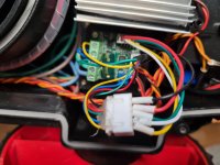
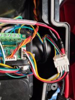
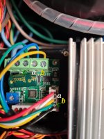
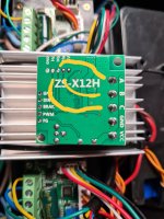
@Sascha and you can try to post the picture of the motor wire color connected to driver.

In all case test the mowing process without any offset with correct 1 turn rev (no need to stop at same time) and the 3ml test and the 360 deg roll.

ok that's good.
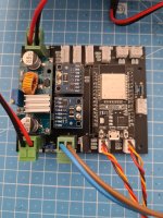
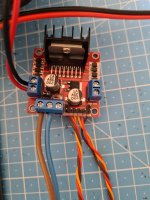
So I hope you can see it a little bit. there are only 2 wiring options. once this with bh to a, ah to b, ch to c, that's my current polarity and then ah to a, ch to b and bh to c. almost everything works the other way around. all other poles interfere with each other and there is only a hum in the motor.
 

Attachments

  • 20230525_191052.jpg
    20230525_191052.jpg
    615.4 KB · Views: 12
  • 20230525_191150.jpg
    20230525_191150.jpg
    829.1 KB · Views: 7
  • 20230525_191111.jpg
    20230525_191111.jpg
    670.8 KB · Views: 9
  • 20230525_192230.jpg
    20230525_192230.jpg
    730.3 KB · Views: 13
Motor links sowie rechts ABC = gelb, grün, blau.
Hallsensoren ABC = gelb, blau, grün. Also blau und grün vertauscht.

Der Mähmotor war anders meine ich.
 
Motor links sowie rechts ABC = gelb, grün, blau.
Hallsensoren ABC = gelb, blau, grün. Also blau und grün vertauscht.

Der Mähmotor war anders meine ich.

Das kann gut sein das bei mir die Hallsensoren jetzt auf abc laufen und ich deshalb am treiber umswitchen musste. Aber ich denke die laufen jetzt gut so. Ist halt nur das nachlaufen des rechten Motors bei den Tests aber das ist ja nicht bei der Fahrt. Wie rum läuft den der mähmotor? links oder rechts herum. Abwohl das ja auch egal wäre am Ende!?
 
Normalerweise läuft ein Motor immer rechts herum, von der Welle aus gesehen... Kann dir das aber nicht mit Bestimmtheit für den Mähmotor bestätigen, da muss ich gucken.
Am Ende ist das egal!
 
hello greets you,

I'm currently putting together the "Perimeter Wifi Sender".
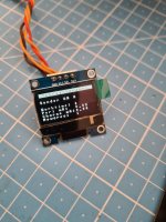
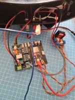
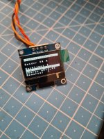
I have Steffan's sketch, which works for him. Oled display also works, but my problem is that it doesn't recognize the Inas, at least it always shows the current value as 0.
I had to swap the pins for Scl and Sda in the sketch because they are the other way round on my Inas.
I've tried a few things, including the ip in the browser..../A1 to switch on the first loop or ..../B1 for the second loop. but the value stays at zero.
The measured volts the motor driver puts out is also only 0.8v to the loop. Input to the motor driver is 10.8 volts.
The Inas are also correctly addressed as in the sketch once not jumpered for the perimeter circuit and once A1 bridged to VCC on the charging circuit. I have 13 Ohms on my Cutwire. Maybe someone had an idea!?
Thanks very much...


Hallo grüßt euch,

ich bin gerade am "Perimeter Wifi Sender" zusammen stellen. Ich habe den Sketch von Steffan, welcher bei Ihm funktioniert. Oled display funktioniert auch, aber Mein problem ist das er die Inas nicht erkennt, zumindest zeigt er den Current Wert immer als 0 an. Ich musste die Pins für Scl und Sda im Sketch tauschen da diese bei meinen Inas anders herum sind. Ich habe so einiges probiert auch im browser die ip..../A1 zum einschalten der ersten oder ..../B1 der zweiten Schleife. aber der wert bleibt auf null. Die gemessene Volt die der Motortreiber ausgiebt sind auch nur 0.8v an die Schleife. Eingang am Motortreiber sind 10.8 Volt. Die Inas sind auch richtig Adressiert wie im sketch einmal nicht gejumpert für die Perimeter Schaltung und einmal A1 auf VCC gebrückt Auf der Ladeschaltung. Ich habe 13 Ohm auf dem Begrenzungskabel gemessen. Hatt evtl. noch jemand eine idee!?
Vielen Dank...
 

Attachments

  • 20230604_110104.jpg
    20230604_110104.jpg
    678.5 KB · Views: 7
  • 20230604_100957.jpg
    20230604_100957.jpg
    1.7 MB · Views: 10
  • 20230604_100405.jpg
    20230604_100405.jpg
    771.8 KB · Views: 9
  • 20230604_100354.jpg
    20230604_100354.jpg
    667.8 KB · Views: 8
  • 20230604_102610.jpg
    20230604_102610.jpg
    927.5 KB · Views: 8
  • 20230604_110108.jpg
    20230604_110108.jpg
    727.7 KB · Views: 7
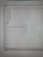
Hast du mal einen I2C Scanner benutzt um zu gucken, ob die INAS gefunden werden und die Adressen stimmen?

Code:
// ESP32 I2C Scanner
// Based on code of Nick Gammon  http://www.gammon.com.au/forum/?id=10896
// ESP32 DevKit - Arduino IDE 1.8.5
// Device tested PCF8574 - Use pullup resistors 3K3 ohms !
// PCF8574 Default Freq 100 KHz 
#include <Wire.h>
void setup()
{
  Serial.begin (115200);  
  Wire.begin (22, 21);   // sda= GPIO_21 /scl= GPIO_22
}
void Scanner ()
{
  Serial.println ();
  Serial.println ("I2C scanner. Scanning ...");
  byte count = 0;
  //Wire.begin();
  for (byte i = 8; i < 120; i++)
  {
    Wire.beginTransmission (i);          // Begin I2C transmission Address (i)
    if (Wire.endTransmission () == 0)  // Receive 0 = success (ACK response) 
    {
      Serial.print ("Found address: ");
      Serial.print (i, DEC);
      Serial.print (" (0x");
      Serial.print (i, HEX);     // PCF8574 7 bit address
      Serial.println (")");
      count++;
    }
  }
  Serial.print ("Found ");      
  Serial.print (count, DEC);        // numbers of devices
  Serial.println (" device(s).");
}
void loop()
{
  Scanner ();
  delay (100);
}
 
Last edited:
The 2 INA226 are on the same I2C bus, so you need to put 2 differents adress using the shunt at back of the INA PCB.
Maybe you forget this ?
 
Back
Top