Richtel
Well-known member
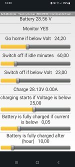
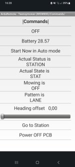
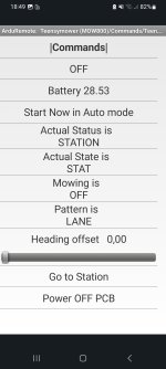
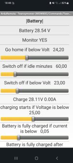
Yes SirPlease share a picture of the arduremote command page and battery setting to see if there is no voltage on the charge side :
 ...
...Yes SirPlease share a picture of the arduremote command page and battery setting to see if there is no voltage on the charge side :
...Jumper 1 is out and i have restartet, but is the sameSomething is wrong in the power PCB.
Mower status=station, so the perimeter is not read.
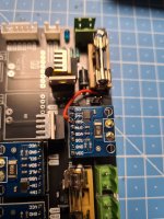
Can you remove the charging jumper and share a picture of the wiring.
.jpg")

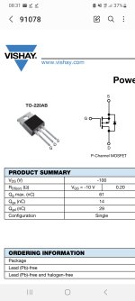
Oh yes, its v1.08 the the last one i think... and the little charge led on Board, is always on!?Maybe INA226 i2c adress issue ?? or diode not in correct direction .
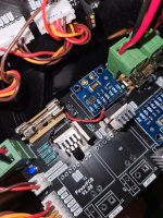
What is the version of the power PCB ?
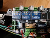
Can you share a picture of the Power PCB ?
For led check the correct direction of D3 diode,Oh yes, its v1.08 the the last one i think... and the little charge led on Board, is always on!?
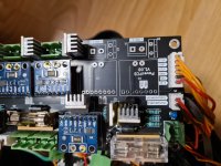
To avoid change on PCB ,Certainly it's more easy to remove (unsolder) pin3 from INA226 U3 and use a wire from U3/Pin3 to output of F1Ok, i will do this work and than i will call back....
So fantastic, You are really crazy and extremely quick at solving problems. Thank you very very much for the quick help.To avoid change on PCB ,Certainly it's more easy to remove (unsolder) pin3 from INA226 U3 and use a wire from U3/Pin3 to output of F1


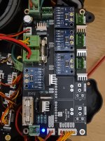
OK, but unfortunately the LED still lights up very weakly. In my opinion, is the diode seated correctly?For led check the correct direction of D3 diode,
OK, I might have figured out what the problem is. The spear diode still lets 2.4v through, which is enough for the LED to glow a little weakly. For example, as soon as I hold the multimeter to the charging sockets on the front and measure it, it goes off briefly because it doesn't seem to have enough juice. I take it away and it glows dimly again...OK, but unfortunately the LED still lights up very weakly. In my opinion, is the diode seated correctly?
I think you can leave the led like that, but i am not sure it's something normal if JP1 is remove : possible Q2 issue
Can you test the automatic charging process ? (When you plug the charger on charge connector you need to see the led ON with strong light and into arduremote (setting battery) the charge voltage need to jump to 29 V and sense to 0.6A or more if battery is not full)
Into basic working mode the Led is mandatory for the station to detect if mower is dock or not and start or stop the sender , But in the last code version you can use WIFI to do that.
It's OK for MOW800 if you have the li-ion charger and battery with BMSBut only with jumper, as it should be
")
It's OK for MOW800 if you have the li-ion charger and battery with BMS
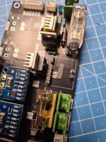
But maybe your PCB have issue in Q2 (certainly shortcut and always on).It can explain the 2.42V on Charge instead of 0V
The correct working mode is made by Q2 : teensy use one output to close or open Q2 and start or stop the charging process according to bat voltage
Jumper is here to bypass Q2 and always charge the battery (teensy don't control the charge and you need a battery with BMS and a real charger LI-ION)
You can leave the jumper and use the mower like that without issue