PowerPCB 1.09

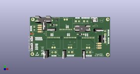
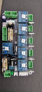
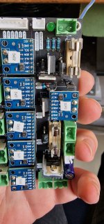
In my setup I just using 4INA‘s and one I2C is more then enough. Therefore it should be as an option.

My problem, all mow motors are connected to I2C1, even with basic setup I have to ise both I2C or bridge both together
 
I can also suggest an INA226 for the charging function/battery and an INA3221 for 3 motors.
That would significantly reduce the size of the board or I could add the step-down for the MainPCB?

The only danger is that it cannot cope with the 3 motors or the 29V
 
Last edited:
Or I put the first 4 Inas on one I2C bus and the other two on the 2nd bus.
Then you only need the second bus if you have more than 3 motors.
 
Or I put the first 4 Inas on one I2C bus and the other two on the 2nd bus.
NO.
Only 3 INA226 can have different adress on standard INA226 PCB.
Maybe 4 ,but never tested on AO and A1 shunt 0x45
So you need to test the solution i suggest
@EinEinfach
DO you have ordered 4 INA226 ?
 
Last edited:
@EinEinfach
Actually i use 0x40 / 0x41 / 0x44 on each I2C line
And i never tested 0x45 / 0x43 / 0x47 possibility

But if you have 4 ina , you can test this:
0x40 / 0x41 / 0x44 / 0x45
And shunt SDA0-SDA1 // SCL0-SCL1

If I2C bus fail with all the INA you can remove the 10K pull-up resistor on the last 0x45 one
pull-up.pngina226-040.pngina226-041.pngina226-043.pngina226-044.pngina226-045.pngina226-047.png
 
Yes I‘m using 4 INA226 on the same bus:
IMG_1716.jpeg
Addresses are defined only by bridging or not bridging A0 and A1 to VCC on the backside
IMG_1717.jpeg
But if I remember correctly much more addresses are possible (16?)
 
Yes I‘m using 4 INA226 on the same bus:

Addresses are defined only by bridging or not bridging A0 and A1 to VCC on the backside

But if I remember correctly much more addresses are possible (16?)
Yes more addresses are possible using shunt on SCL or SDA and not on VCC (my picture on 0x43 and 0x47).
But like i say i never test this possibility.

adress 69 for you is 0x45, so if it's work on your test and on this adress: you win (y)

If all other shunt are OK it's possible to build the PCB with only one I2C line, But need again to confirm the issue with all the pull-up resistor on I2C line (you have one on each PCB, so 6 ????)
 
Exactly that is my configuration. My wish was to add two jumpers to new PCB to make possible shunt both I2C
Yes it's OK ,or simply remove the second I2C line.
Did you test with the 4 INA for a long duration ?

I don't know exactly the price of a PCB already assembled by JLCPCB with directly INA226 ship and R010 resistor,It's other possibility
 
Ok, here's what I've thought about.
I will now order a bug-fixed version of the current PowerPCB in order to remain compatible with the current Teensys version so that no code changes have to be made.
In addition, I will create a new PowerPCB, but only for 3 motors, with all INAS on one I2C bus.
If the size fits, I would also put the step-down converters on there, then they have a fixed place.

If you have more motors, you can use the large PowerPCB or 2 small PowerPCBs.
I think this is a good compromise.
 
So here is the PCB with only 4 INAS.
Unfortunately it hasn't got any smaller, but I can't get it any better aligned.
 

Attachments

  • charge_pcb.jpg
    charge_pcb.jpg
    129.9 KB · Views: 12
  • charge_pcb.pdf
    63.1 KB · Views: 3
Yes, the Polyfuse are not really easy to get, but they fit in there, Bernard did too.
I also still have so many of the fuse holders
 
In my opinion it also better to take smd parts where possible, not to small not less then 0805 package. I don’t know why do people hate smd, it’s not a rocket science to soldier that. And in most cases the parts are 5 times cheaper then regular parts. E.g. a regular resistor costs 0,12cents and 0805 smd just 2cents.
 
Unfortunately I don't know anything about the SMD things, but it would certainly be possible to switch to them, then I can have them fitted by jlcpcb.
But not with this version, I need a few first so that I can get started again.
 
I need to come back to Q4 and Q2. The datasheet of IRF9540 says that the GS- Voltage must not exeed 20V. I think we overload both IRF if they are switched on.
Gate is grounded and Source is 24+ Volt.
Or I'm wrong?
 
I've modified my V1.08 PCB to prevent both MosFet from to high Ugs and it works perfectly. Ugs will not exceed 10V (Uz) which is inside specs.
May in V1.10 we should recognize it. For the 1k Resistors I used 2x2k in parallel because of the needed power.
 

Attachments

  • Charge_108_mod.PDF
    379.8 KB · Views: 7
  • 20240407_161329.jpg
    20240407_161329.jpg
    850.1 KB · Views: 6
  • 20240417_171311.jpg
    20240417_171311.jpg
    650.6 KB · Views: 6
  • 20240417_171321.jpg
    20240417_171321.jpg
    757 KB · Views: 6
Oh cool, if it works like that, I'm happy to take it over.
I can see from your pictures that you have the jumper on J1, which deactivates the charge control. If you don't want that, then you should remove the jumper
 
Back
Top