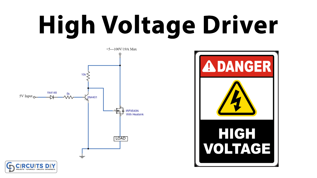
Ich habe den Schaltplan der PowerPCB noch einmal überarbeitet, allerdings bin ich mir bei den IRF9540 MOSFET nicht sicher, da habe ich unterschiedliche Schaltpläne im Internet gefunden, das muss noch getestet werden.
Mir fehlen gerade Kabel um das auf dem Steckbrett nachzubauen, sind aber bestellt.
Aber vielleicht kann das ja mal jemand testen.
I have revised the circuit diagram of the PowerPCB again, but I am not sure about the IRF9540 MOSFET, I have found different circuit diagrams on the Internet, this still needs to be tested.
I don't have the cables to rebuild it on the breadboard, but they have been ordered.
But maybe someone can test it.
 www.circuits-diy.com

Mir fehlen gerade Kabel um das auf dem Steckbrett nachzubauen, sind aber bestellt.
Aber vielleicht kann das ja mal jemand testen.
I have revised the circuit diagram of the PowerPCB again, but I am not sure about the IRF9540 MOSFET, I have found different circuit diagrams on the Internet, this still needs to be tested.
I don't have the cables to rebuild it on the breadboard, but they have been ordered.
But maybe someone can test it.
Arduino High Voltage Driver Circuit Using IRF9540 Power MOSFET
Control current/voltage requirements are often higher than what can be handled directly. Today, we will build an Arduino high voltage driver
www.circuits-diy.com
Attachments
Last edited: