EinEinfach
Well-known member
Der müsste super funktionieren
https://www.cytron.io/ampp-13amp-6v-30v-dc-motor-driver
https://www.cytron.io/ampp-13amp-6v-30v-dc-motor-driver
/*BTS7960 Motor Driver Carrier*/
//const int MotorRight_R_EN = 8;    (VCC) to Arduino 5V pin
//const int MotorRight_L_EN = 9;    (VCC) to Arduino 5V pin
const int pinMotorRight_forward = 2;   //(RPWM) to Arduino pin 2(PWM)
const int pinMotorRight_reverse = 3;   //(LPWM) to Arduino pin 3(PWM)
Was ist nicht ganz richtig?Nicht ganz richtig, aber er braucht 2x PWM für vorwärts/rückwarts
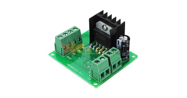
Müsste gehenDann sollte so einer auch funktionieren:
Orange sind 5V Versorgung für Hall Sensoren und Driver (diese Variante braucht auch 5V)Wenn ich deinen Schaltplan richtig interpretiere, dann ist der orange Anschluss ein Ausgang?
Ja, die muss einmal an DIR Pin und falls Odometrie mitgemessen soll, dann noch an MCU angeschlossen werdenSorry ich meinte die blaue Leitung HALL OUT
Cool ..So I think I'm nearly complete with my PCB design. If someone wanna review it, it will be great.
KicadFiles
Ok thanks, will doublecheck footprintCheck the footprint of the DC/DC stepdown to use a minimum 3A one and not a simple LM2596 (XL4005 for example)
Yes make senseIf possible increase the width of the trace between J26 and PI4 and add a jumper or fuse to adjust 5V on DC/DC before powering the PCB by 5V.
Yes it works well on my test build. But I didn't perform long term tests. What is exactly failed in your configuration?I suppose J9/J10 etc ..... are for level shifter (Did you test this connecting :Signal is reverse) and did they work with red BL motor driver ZSX11H odometry pin (My own test fail !!!!) ??
Indeed, it will be better, but I didn't find out how to speak to pico over usb in micropython. Maybe USB_VCP could be a way. For flashing actions the usb cable can stay connected inside the roverI don't know how pico work, but on teensy it's better and faster to connect PI/Teensy over USB than using Serial, it's certainly also more easy to flash pico from Pi over USB .
Ardusimple Board will be connected via USB to RPI4Where did you connect the RTK GPS ?
There is no level shifter, don't know what you meanWhy level shifter between IMU and PI ? GY521 is 3.3V module
Hiere is also no level shifter, don't know what you meanWhy level shifter also to Power PCB I2C line ?
Can try to get more placeAnd last remark DC/DC generate a lot of EMF noise , so I2C line and IMU as far as possible from it
Sorry i have thought that J24/J25 and J14/J15 are the location of the Level shifter but not at allThere is no level shifter, don't know what you mean

It was 2 years ago a very fast test,so i don't remember exactly , and finally it was all OK at 3.3V from teensy output .Yes it works well on my test build. But I didn't perform long term tests. What is exactly failed in your configuration?
OK.Indeed, it will be better, but I didn't find out how to speak to pico over usb in micropython. Maybe USB_VCP could be a way. For flashing actions the usb cable can stay connected inside the rover
Perfect.Ardusimple Board will be connected via USB to RPI4
")
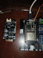
Oh very cool!! Can‘t wait to know how is it workThe Cytron Motordriver arraived, verry small. Same sizes as the ESP32 V1