You are using an out of date browser. It may not display this or other websites correctly.
You should upgrade or use an alternative browser.
You should upgrade or use an alternative browser.
Start Probleme
- Thread starter Richtel
- Start date
Richtel
Well-known member
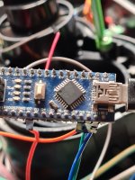
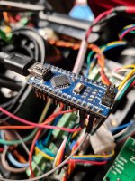
Yes i have a Arduino Nano or Micro or Pi PicoDo you have an arduino uno or mega or a 5V logic mpu?
Richtel
Well-known member
Here code i use to test the driver with a mega , maybe you can adjust for the nano
And the video result
Hello Bernard.
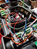
thank you very much for the sketch. I wired and connected everything. the engine only jerks quietly, only briefly at regular intervals. is that normal!?
Code is write for arduino mega , so maybe so need to adjust it if you don't have a mega , please send a picture of your wiring and the code you use if you have change something.
I found the test motor and driver i use in the video, so i can try to do the same on my side.
I found the test motor and driver i use in the video, so i can try to do the same on my side.
Richtel
Well-known member
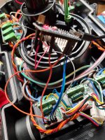
the code and pinout is the same. I rewired everything again, but now he's doing something a little irregularly. I made a video...
Attachments
Richtel
Well-known member
Herein Arena videos
Yes....What about the console result ?
The last number is the Odometry , Did it change from 5000 to 5500 ?
Attachments
Yes it' s strange , normaly wheel need to rotate in one dir and reverse after , so the dir pin is not OK.
For the PWM freq you can add this line :
and comment out this one
also code is write to move a load on positive and negative torque on the motor
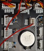
THE MAIN result is that the odometry is OK, so something is strange on the main PCB ,I need to test on the last PCB version , maybe the resistor for voltage divisor is not OK ?
For the PWM freq you can add this line :
Code:
void setup() {

  TCCR1B = TCCR1B & B11111000 | B00000010;

  motorLeftSpeedRpmSet = 30.0 ;
  odometryTicksPerCm = 22 ; // encoder ticks per cm
and comment out this one
Code:
  attachInterrupt(digitalPinToInterrupt(pinOdometry), plus, RISING);


/*
  int myEraser = 7; // this is 111 in binary and is used as an eraser
  TCCR2B &= ~myEraser; // this operation (AND plus NOT), set the three bits in TCCR2B to 0
  int myPrescaler = 2; // 1=31Khz 2=4Khz
  TCCR2B |= myPrescaler;
  */
  delay(3000);
also code is write to move a load on positive and negative torque on the motor
THE MAIN result is that the odometry is OK, so something is strange on the main PCB ,I need to test on the last PCB version , maybe the resistor for voltage divisor is not OK ?
Nothing has actually changed to the previous.THE MAIN result is that the odometry is OK, so something is strange on the main PCB ,I need to test on the last PCB version , maybe the resistor for voltage divisor is not OK ?
I have installed the 1.03, it works for me.
But of course you can also test it with the PCB.
Yes it's also ok for me on 1.03 with the ZS-X11H,Nothing has actually changed to the previous.
I have installed the 1.03, it works for me.
But of course you can also test it with the PCB.
I have only tested the ZS-X12H on the 1.02 PCB version. And I need to check the value of the divisor resistor i have solder on the PCB1.02 maybe i use different one ?
Richtel
Well-known member
Genau das tut er leider nicht ganz und deswegen gibt's wahrscheinlich troubleAh ok I have also only installed the ZS-X11H.
But it shouldn't be the voltage divider if the driver outputs odometry in 5V.

