Teensy PCB Ardumower (T-Mow)

D18,D19 are Tx/Rx-Pins in your PDF (github, Ardumower_teensy_pro), and D20,D21 are SDA/SCL-Pins.
At the moment, i do not use Sense feedback of the two frontmotors.
I have already made a plan for the pin assignment. The pins of the Teensy are not enough so I wanted to make a port expansion. I asked you for the complete circuit to see what you do with the esp32.
One way to reduce the pin count would be to replace the ultrasonic sensors with TOF sensors with i2c.
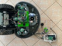
Since i use the stepper motor for steering, the signals from the ultrasonic sensors are very poor. I did not have this problem when using servos. One reason is also that the control of the stepper is in the back and the stepper in the front of the mower.
Maybe you can post the pinout of Teensy and esp32 in github, then I can see how far it fits for me.

Gruß Fürst Ruprecht
 
Maybe you can post the pinout of Teensy and esp32 in github, then I can see how far it fits for me
I don't understand exactly what is for you the pinout ?
You have on github the full kicad schematics of the PCB with all the connected PIN between Teensy /ESP and the PCB.
Here the github location (maybe you use other one because i don't use the name Ardumower_teensy_pro)

See Power_PCB_V106 for the battery and motor sense management
And Teensy_PCB_V101 for the main PCB with tennsy and ESP32.

I attach the PDF of the Main PCB
 

Attachments

  • Ardumower.pdf
    152.1 KB · Views: 23
OK, these files look different. Thank you.
(I made a ZIP download from your github page yesterday. Maybe something went wrong.)
I looked at your signal assignment of the Teensy4.1 pins. The deviations are somewhat larger, so it doesn't make sense for me to use your board layout. Nevertheless, thank you very much for providing your documentation.
I don't think I'll be working on the mower for the next few weeks, there are other things that need to be done.
But I would like to have a look at your software for next year.
Do you have experience with TOF sensors? Since I have been using the stepper motor, the ultrasonic signals are very disturbed. So I thought one possibility would be to switch to e.g. VL53L1X.

Gruß Fürst Ruprecht
 
Do you have experience with TOF sensors? Since I have been using the stepper motor, the ultrasonic signals are very disturbed. So I thought one possibility would be to switch to e.g. VL53L1X.
Yes but only VL53L0x unfortunatly a bad experience .
Perfect inside a when testing but always fail in full sun.
You can see the code for arduino UNO and 3 laser sensor VL53L0x

denna towel2.jpgtowel1.jpgtowel3.jpgtowel4.jpg


The deviations are somewhat larger
I don't understand ?
 
I need more Pins: 3xSonar, 2+2xDriveMotor(Enable, Dir, PWM,Fault,Sense)(Odometrie?), 3xBumper (left,right,back), 4xRF-Controler, 1xSteppermotor (and light for fun). So i planed with 16-channel digital- an 8-channel analog-expander (need sda/scl, interrupt).
 
Hi @Bernard
can you give a small update for the Software/PCB?
Are the instructions for the Teensy software the same as for Azuritber?
 
Here are some picture for simple mower with power control and only one mow motor (Tianchen TC-G158) from @Bernard
 

Attachments

  • PCB.jpg
    PCB.jpg
    705.2 KB · Views: 20
  • Mower.jpg
    Mower.jpg
    1.2 MB · Views: 20
And the RL2000 with 3 big mow motor and full option RFID PI vision buzzer etc...
 

Attachments

  • rl2000 teensy 1.jpg
    rl2000 teensy 1.jpg
    1.1 MB · Views: 18
  • rl2000 teensy 2.jpg
    rl2000 teensy 2.jpg
    1 MB · Views: 17
  • rl2000 teensy 3.jpg
    rl2000 teensy 3.jpg
    1 MB · Views: 17

Attachments

  • teensy_gerber_v1.02.zip
    329.3 KB · Views: 11
  • Power_PCB_v106_gerber.zip
    155 KB · Views: 7
I will order some circuit boards today. Anyone who is interested can get in touch.

Ich werde heute ein paar Platinen bestellen. Wer Interesse hat kann sich melden.
 
@Sascha Do not forget the change on the level shifter resistor for receiver and odometry if needed
Optionaly it's also good to add a heat sink on Q4 for big mower (when 10 Amp total power are needed ) (I add one on my RL2000, but it's dificult with space).

@LaurentS if you want i can send you the last kit i have.
 
Hi @Bernard
The Odometrie is like you have post it here
What do you mean with receiver?
Optionaly it's also good to add a heat sink on Q4 for big mower (when 10 Amp total power are needed ) (I add one on my RL2000, but it's dificult with space).
Next Version, i have made the Order.
 
Hi @Bernard , thanks ! But... I've already ordered PCBs... well, each time I order blue ones... and I can't wait....:) but no problem if someone needs PCBs, they could already have blue ones ... or green ones. :) (... wir haben bald alles im Lager... :D )
I need only 2 kits for me.
 
HAHAHA yes, good choice ! :D I have now to find all the components, but if I correctly understood, there's a possibility to upgrade step by step the mower and add options when the previous one is ok, is it correct ?
 
Here is a small description of Components you will need:
For Mower you need:
Chassis
2x Motors with Hall Sensor for Odometrie (Mowing)
1x Motor (Cutter)
1x Battery 24V (29.4V)
1x Charger
Motordriver LM2596/BTS7960
Optional:
Bumper (Microswitch)
Sonar Ultrasonic

MainPCB:
JST XH 1x04 P2.50mm
JST XH 1x03 P2.50mm
JST XH 1x02 P2.50mm
JST XH 1x05 P2.50mm

TerminalBlock bornier-2 P5.08mm

Resistors:
1kO
1.5kO
100k

Diode:
1N5819

Power Switch
Buttons
Speaker/Buzzer
LED 3.0mm
Jumper
BatteryHolder Keystone

GY-521

Teensy4.1
ESP32-DEVKIT-V1

PowerPCB:
TerminalBlock bornier-2 P5.08mm

INA169
Fuseholder
Fuse 10A
Fuse 5A
LED 3.0mm

Resistors:
4.7kO
10k
100k

IRLB 8721
BC547C
SB1240 1N5819
MBR1045
1N4148
Elko 100uF

Some Pin Header
BOOM File for PowerPCB
BOOM File for MainPCB
 
Last edited:
Back
Top