Teensy PCB Ardumower (T-Mow)

@LaurentS
Shopping List is on Github.
Some of the names and links are in German, but I hope you can still find everything.
I have tried to find a link for everything. I hope I have not forgotten anything. And they are all just examples.
All information without guarantee

Motor drivers and motors are still missing.
You then need a housing, motors, motor drivers, battery+charger and perimeter transmitter and charging station.

For motors, I would look for defective robotic lawn mowers on Ebay, it's cheaper and you have matching motors right away.
As Bernard has already written, Brushless motors are not yet supported. But that will still be come soon, as I have some myself.

@Bernard
Since I have brushless motors and drivers, I can deal with it. For this, the code has to be modified a little.
 
Last edited:
Sascha, on the first TeensyPCB Excel dok you sent me, JST connectors were with a 2.5 pitch and not 2.54; which one is correct ? Thx.
 
The 2.54 definitely fit and the 2.5 should also fit.
I don't think there's really a difference, I've already ordered both because I couldn't find them in the right pin count.
 
Thanks, it seems good for now; I have to choose options , but the most is now on the list. :) for Ulrasonic sensors, HC-SR04 seems to be a better choice than JSN-SR04T ones: many people report problems with this last reference.
Just take care that the fuse holder is a 6A and one of the two fuse that you have to install is a 10A one.
Perfect for the ESP32 it's the good one ! Thanks ! :)
 
Last edited:
For Ulrasonic sensors, both work but if you don't want to have fake detection you need to use them at small distance (<30cm).
I have thought that HC-SR04 have trouble with rain or humidity ,but one year test show a correct result.
Same for 3D printing no problem for me , i have some PETG or PLA parts printed 5 years ago (PRUSA MK3) and never trouble (RFID box or coil box or sender box)
You only need to use PETG on part where temp can be >50 Deg like motor box or arround PCB and Battery.
 
Thanks Bernard for your informations; I saw on a video that JSN-SR04T don't give informations if you are on a distance<21cm. They stay on those 21cms. I have my 3D printer since 2 months and never printed petg. I'm using PLA+ from GST3D. I will start my project by printing the PCB Box and Battery carrier... well, PETG will be soon necessary.
 
Thanks Bernard for your informations; I saw on a video that JSN-SR04T don't give informations if you are on a distance<21cm. They stay on those 21cms. I have my 3D printer since 2 months and never printed petg. I'm using PLA+ from GST3D. I will start my project by printing the PCB Box and Battery carrier... well, PETG will be soon necessary.
Yes JSN-SR04-T is not OK at very small distance.
For PLA be careful in hot location (>45 50 Degrees) and normaly not OK for battery or PCB in full summer.
PETG is better and can do the stuff .ASA is more complex (but it's my own experience).

So PLA for standard temp location / PETG or ASA for high temp location.
 
Hi Bernard and Sasha,
could you tell me for what is (or are) the XL4015 5A DC-DC power supply used for ? Thanks.
 
Last edited:
Thanks Sascha. You know, it's not really easy to understand what is connected to the PowerPCB and the MainPCB, like small PCBs for control, etc... I'm actually on dissecting each Bernard's photos or videos to understand all this salad of connections... :D 
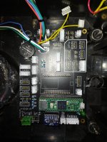
really nice project, but it's important to understand where all parts have to be installed (like small pcb's) before printing, to know if there is already enough place for each part.
 
The PowerPCB and the MainPCB are connected to the 6x1 JST-XH (J16) and the 2x1 JST-XH (J17).
Otherwise, all connections are actually labeled. But if there are questions, no problem.
I have not yet found a program with which I can record where what goes.
I'll have to ask Bernard what he used there.
 
Here are 2 Pictures
 

Attachments

  • IMG_20211212_174839.jpg
    IMG_20211212_174839.jpg
    1.1 MB · Views: 19
  • IMG_20211212_174825.jpg
    IMG_20211212_174825.jpg
    1.1 MB · Views: 19
The PowerPCB and the MainPCB are connected to the 6x1 JST-XH (J16) and the 2x1 JST-XH (J17).
Otherwise, all connections are actually labeled. But if there are questions, no problem.
I have not yet found a program with which I can record where what goes.
I'll have to ask Bernard what he used there.
I am sorry but i spend more time to test and dev than explain.
But this week i can draw the full wiring diagram .
I use illustrator but certainly it's not the easier way
 
No Problem, testing and DEV is much more important.
I finally managed to get my engines running.
But apparently 2 motor drivers are broken, nothing happens anymore. I just ordered new ones.
These things are really stubborn and don't match the descriptions of how they are supposed to work.
 
Last edited:
Woww Sascha ! your name is Speedy Gonzales ! :D I haven't received my PCBs yet.
Don't worry Bernard and Sascha, I really understand that you have to spend much of your time in tests and dev ! the chance is that you share your research. Your vidéos are quiet helpfull when you filmed your PCBs :D Thanks for all !!! I'm so happy that I found such a source for my futur mower ! : :) I've just dreamt of it before.
Which motors do you have, Sascha ?
 
Last edited:
Back
Top