To avoid drive motor shake on manual stop i have add a OFF command and certainly it stop also the mow motorI turn Testing ON
To test the mow motor you need to first drive forward in manual mode and start mow motor.
To avoid drive motor shake on manual stop i have add a OFF command and certainly it stop also the mow motorI turn Testing ON
Yes It's a big value but it can work , Can you check in test ODO if the noise is not very high in the middle of the area.Last time I looked, MAG was between 7000-8000 can that be or is that too much?
I have not installed RFID yet
Bernard, do you think it's not a good idea to install thoseones ? I don't want to bore the body for finally not installing thoseones.Remember that sonar are not really reliable,.I spend a lot of time on it and you need to order 10 of them to have 3 with a correct detection. other detect objet when nothing in front .
Can you use the console to see the error .n the middle of the Garden with Error.
I don't want to say that they never work ,but it's better to not bore the body and first use mower with Bumper ,perimeter and motor sense.I don't want to bore the body for finally not installing thoseones.
") .
.")

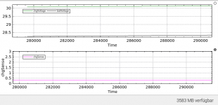
Time;chgVoltage;chgSense;batVoltage
0;0;0;0
0;28.76;4.1;25.32
60;28.77;4.1;25.43
120;28.78;4.1;25.5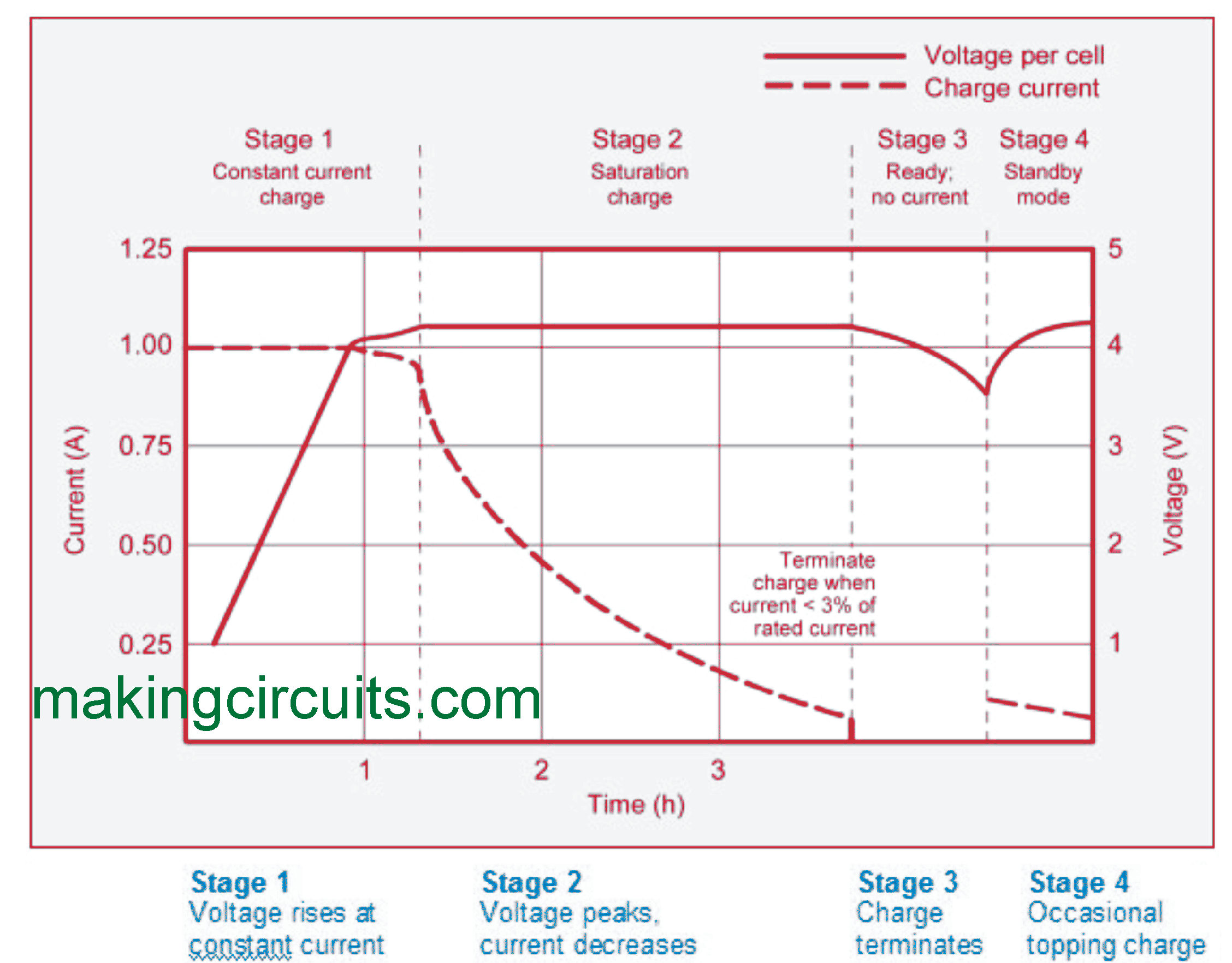
180;28.79;4.1;25.54You need to check the start and stop voltage .It's possible it's a fast charger and use only the CC mode.it takes about 2 hours until the battery is full
 makingcircuits.com
Ah yes you are right.If it was with the R100 resistor the value 4.5A can be totally wrong.