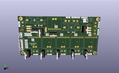
Since the last PowerPCB was complete rubbish and a lot of errors crept in, I have now completely revised the PowerPCB again.
I have placed the components a little differently in order to achieve a better routing of the conductors.
In addition, there is now a jumper to bypass the charging function. If the jumper is bridged and the mower is in the charging station, it always gets power from the charging station.
The footprint of the blocking diodes now also fits, it was the wrong way round before.
Please check everything carefully so that I can order the new PCBs.
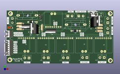
")