New Batch of PCB's

Sascha

Administrator
Staff member
I would like to order a new batch of boards in the next few days to test them.
But I would like to know before if there are any suggestions for improvement or extensions that you can think of?
If the batch is bug-free, I would start advertising the Teensymower Project to make the project a bit better known.

I would therefore be pleased to receive feedback.

If you are interested in PCBs, please contact me, the more testers the better :)

Current state 05.04.22:
MainPCB:
Voltage divider odometry and perimeter: corrected
Placement of some connectors optimised
Replacing ESP32 V.1 with ESP32 current model (40 pin) not yet done

PowerPCB:
One track has lower cross-section: not done

PCB charging station:
Finding phase
 
Last edited:
Sascha,
kannst Du mal den Spannungsabfall an den Mosfets messen.
Ich habe Bedenken, daß (bei mir) aufgrund des Spannungsabfalls die Ladeobergrenze nicht erreicht wird.
Das kann aber an meiner abweichenden Auslegung liegen (auch wenn ich es nicht verstehe).
Wenn ich das Gate von Charge+ über 4k7 anschließe, wird der Spannungsabfall auch nicht geringer, liegt bei ca. 2V.

Gruß Fürst Ruprecht
 
Ja kann ich machen, wenn mein Motortreiber da ist und ich ihn nochmal auf mache.
 
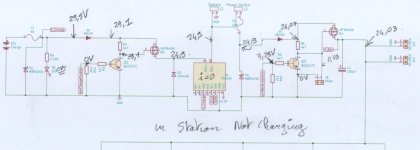
Here picture of the voltage measurement on Power PCB.
No voltage drop on the mosfet ,only on diode D2 and D5 and it's normal (On the Pcb it's not SB1240 ) but all other component are the schematics one.
Battery is 7S3P 10A with BMS and charger is the one from Marotronics shop , but it's poor quality.
It's take more than 10 Hours for a full charge !!!!!
.
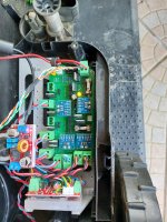
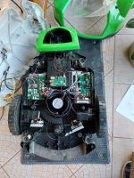
Numérisation_20220404 (2).jpgNumérisation_20220404.jpg20220404_194222.jpg20220404_194216.jpg
 
It's the bumper.
It's compose of 4 KY003 magnet sensor , and the green cover of mower is movable .
 
Today i try to mow on very high grass and set the max mow power to 90 W .
Result: i destroy the Mosfet and FUse !!.
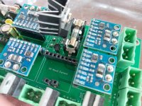
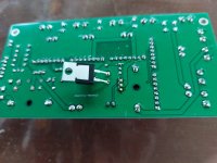
It's better to add a radiator on it to avoid this and add space on PCB .
 
heatsink .
Or connect the mow motor 24V after Emergency swith directly to battery ??
 
I had the same problem today.
After I finally got the cutter motor running, I changed it. It was very loud, the replacement is quiet. But also gets warm/hot very quickly.
Then I took it in the garden and let it run in automatic mode and after 2 minutes it stopped, no more power.
The fuses are intact but the 24V is disappearing somewhere.
I have to check everything and think about the PowerPCB again.
 
It's really append to me on extreme condition.
Mower max PWM to 250 and power max to 100W.

But in my case the BL driver was always cold, Are you really sure about the wiring ??

Here my workaround:20220405_184832.jpg20220405_184839.jpg
and a video of the mower running on high grass.
 
Max PWM was set to 240 and 90W max Power.
The Motor Driver was cold only the Motor was hot.
I have tried many combinations of reverb cables and the way it is now is the only way it turns, otherwise it just hums. Maybe I haven't tried all the combinations, maybe I'll unscrew the motor.
 
Motor was hot.
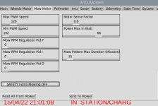
40 Deg is possible, in my case actualy the max power is reduce to 66W and PWM between , so firmware stop the motor on very very high grass.

Here my setting:
Capture d’écran 2022-04-15 210120.jpg
 
Ok I will test it again, but first I have to find the broken part on the PCB, i can't see anything burnt.
 
However, I don't really understand why this is happening.
From the data sheet, BC547C and IRF9540N should be ok, but I am a layman.
 
Hi Bernard and Sascha, I think I will do the same as Bernard: to weld those components on the back of the PCB and try to add an heatsink or... order the new PCB.
 
Back
Top