You are using an out of date browser. It may not display this or other websites correctly.
You should upgrade or use an alternative browser.
You should upgrade or use an alternative browser.
New Batch of PCB's
- Thread starter Sascha
- Start date

@Bernard
Bernard I have now found Footprint for BOB-12009 from SparkFun.
If I count correctly, we currently need 9 level shifters, with 3xBOB-12009 we have 12 available, with an 8 we have one too few")
But I can also make the resistors and two TXB0108 in SMD and have them assembled by jlcpcb, so you only have to assemble the connectors and pin headers yourself.
What do you say?
Bernard I have now found Footprint for BOB-12009 from SparkFun.
If I count correctly, we currently need 9 level shifters, with 3xBOB-12009 we have 12 available, with an 8 we have one too few
But I can also make the resistors and two TXB0108 in SMD and have them assembled by jlcpcb, so you only have to assemble the connectors and pin headers yourself.
What do you say?
Be careful :
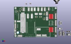
My electrical test actually show : (small level shifter and MCP23017 at the top right of the picture)
1 / For red driver ZS-X11H V1 the level shifter is not needed,PWM work at 3.3V and brake also, so you can use the EN pin like in PCB V1.01 to brake and simply some minor change in the code can mange this feature.
2 / using level shifter invert the signal (maybe not the TSX0108E) , so on startup or code upload motor can run at full PWM and it's very dangerous.
3 / MCP23017 work well for blinking led ,manage the motor Dir but fail to command the brake on motor driver (I don't understand why).
Here the component i have not tested:
-Black BL driver.
-Other Red Driver ZS-X11H but the V2 version !!
-8 pin level shifter from marotronics
-TSX0108E level shifter
The small blue 4 level shifter on the picture is the same as the one from Sparkfun.
I'm leaving them on the board now, if you don't need them you can bypass the pins or I'll leave it out completely and we'll just work with 3.3V on all the motor pins, like we do now.
These are also costs that can be saved.
What is the difference between the ZS-X11H V1 and V2?
I would have to look up which version I have, I can't tell.
OK.I'm leaving them on the board now, if you don't need them you can bypass the pins
Maybe they are needed for JYQD ?
I don't know and can't find it on the net.What is the difference between the ZS-X11H V1 and V2?
Up to now i always use the V1 driver.
I hope on the V2 motor can reduce speed with more brake torque.
The JYQD also worked for me with 3.3V.
As far as I know, 3.3V is also sufficient for the DC motor drivers.
So we don't actually need the level shifters at all, if I'm right?
I would leave them out.
Then I would also leave them out and the board is only error-cleaned (voltage divider) and the labelling revised.
The components will be positioned slightly differently for an optimized circuit path.
I don't think , if you remember there is a problem with the dir changing that generate a long delay on one wheel at not the other.The JYQD also worked for me with 3.3V.
Today i have tested the small 4 channels level shifter It's work like expected with the red driver including the ODO high frequency.
so 2 solutions you don't use them at all and the PCB is OK for red driver or you can test again the JYQD using a level shifter on the enable pin to see if the delay is gone.
The odometry is also OK using the level shifter at full motor speed , so you can use it or not (resistor is also OK)
Yes it's OK at 3.3V for DC motor.
I have also tested the TSX0108 and it's not OK (certainly need pull down resistor on all pin ?? !!!!).
Maybe you can test the JYQD with the small level shifter ??


@Bernard Here the Break seems to Work.
Rutschen den Hang runter, warum bremst der Mower nicht
Hallo zusammen, mein Mower rollt den Hang ohne zu bremsen runter. Kann mir jemand sagen, wie ich dieses Verhalten korrigieren kann. Hier kleines Video um das Problem zu verstehen: Passen meine PID Parameter nicht? Der Mower sollte doch mit den Gear Motoren durch rückwärtsdrehen oder...
forum.ardumower.de
Yes brake also work for me on wheel motor , the issue is i did the test on big mow motor at pwm=255 and i have tough that D8 can stop the voltage feed back and it's not the case.
I need to build a test to record the voltage and sense feed back on big mow motor .
Maybe need a big capacitor or load resistor to absorb the braking energy.
Actualy i have big trouble because a huge hailstorm destroy my car , the roof and other part of my house ,so time left for mower dev need a small brake
brake 

I need to build a test to record the voltage and sense feed back on big mow motor .
Maybe need a big capacitor or load resistor to absorb the braking energy.
Actualy i have big trouble because a huge hailstorm destroy my car , the roof and other part of my house ,so time left for mower dev need a small
brake