New Batch of PCB's

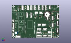
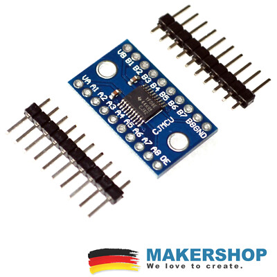
So I have now only corrected the known errors on the PCB, extended and partially enlarged the labelling and sorted the components a little differently in order to optimise the tracks a little.
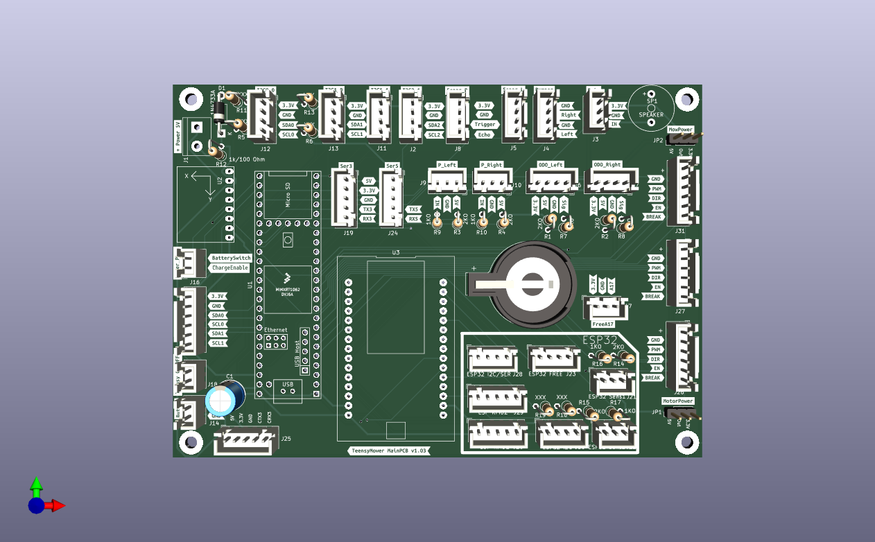
I haven't added the brake pins for the motors yet, the Teensy only has 4 free pins.


Teensy_MainPCB.png
 
You can test by using the EN one over a level shifter and adjust code like that:
Code:
void setBL500W(int pinDir, int pinPWM, int pinEnable, int speed) {
  if (speed ==0) {
    digitalWrite(pinEnable, LOW) ;
    return;
  }
 
  digitalWrite(pinEnable, HIGH) ;
  if (speed < 0) {
    digitalWrite(pinDir, LOW) ;
    analogWrite(pinPWM, ((byte)abs(speed)));
  }
  else {
    digitalWrite(pinDir, HIGH) ;
    analogWrite(pinPWM, ((byte)abs(speed)));
  }
}

The brake pin is not the main issue because I have a small slope near the wire and the Red BL driver can't manage the speed (mower go too fast across the wire but PWM is low) , so we need to find a BL motor driver with fast response time .
On flat surface everything work better than the brushed motor.

I need to find time to connect the MCP23017 over a 5V level shifter and use it for EN and BRAKE at 5V level
 
First Draft of MainPCB 1.03. Main changes are the Bidirectional Level Shifter on Page 2 and Protection Diode.
 

Attachments

  • Teensy_MainPCB.pdf
    194 KB · Views: 5
  • Teensy_MainPCB.png
    Teensy_MainPCB.png
    197.2 KB · Views: 7
First remember that we need something simple with less component possible,so i recommend level shifter already build PCB like this one :
or this one :
The second one have a 0E pin that can help on PCB startup.

It's OK for the input 5V protection , but need to check the sense that can go across R11 and D1 ,maybe a 24V can always destroy everything.
It's OK for level shifter on free01 but see my initial recommendation.


You don't need level shifter on perimeter and ododmetry because it's mandatory high frequency input ,so 2 simple resistor can easily do the job.
Level shifter is use for bidirectional line like I2C or on more than 3.3V output like you do with motor mow brake.
Also level shifter on PWM pin need a high frequency component and need test to be sure it can work.

I work on it and send you my vision of the new PCB including Level shifter and MCP23017 ,but without real electric test
As i don't have lot time left , so certainly it's better you order first your version and i do my best on my side.
 
OK i can Change it for Perimeter and Odo.
I like that better, too. I would still leave the level shifter for EN for the motors. Do the Drive motors also need the brake or can I leave it out?
If you have a footprint for the breakout boards, then I can install them later. I have not found any. I also searched for an ic but didn't find one either.
 
If you have a footprint for the breakout boards,
No but i have order a TXB0108 and i can create the footprint when i receive it.
For ESP32 dev kit V4 i have tested one and it's OK but not find the footprint, so certainly i also need to draw it :mad:

For EN and Brake :
The brake option is only available on ZS-X11H driver and XY-BLDC (not tested) and not on JYDC ,so you can do like that:
Simply add level shifter on the 3 enable pin : PinMotorRightEnable,PinMotorLeftEnable,PinMotorMowEnable and on the 3 DIR pin

For ZS-X11H driver the PCB enable pin is connected to Brake function. Dir is OK at 3.3V
For JYDC driver the PCB enable pin is connected to EN function. Maybe the DIR need also a level shifted ?????

Or you can use Free01 , Free02 and FreeA16 as PinMotorRightBrake etc.... for New Brake possibility .
 
The two EN pins for the drive motors can also be combined, as they are both activated at the same time.
Footprint for the ESP is in kicad, at least with me. But I am not at home right now to say the name
 
I'm not sure if I can get it all on the board without making it bigger.
I might have to remove the ESP32 connections, except for RFID.
 
I'm not sure if I can get it all on the board without making it bigger.
I might have to remove the ESP32 connections, except for RFID.
You can remove the esp32 connection only keep the 2 RFID like you suggest.
I work actualy on the 4 WD PCB with mcp23017
 
So here is the current wiring diagram again, please take a close look to make sure I haven't forgotten anything.
 

Attachments

  • Teensy_MainPCB.pdf
    220.4 KB · Views: 5
So here is the current wiring diagram again, please take a close look to make sure I haven't forgotten anything.
No particular remark.
Maybe you can rename Free01 /02 and A16 to correct desi like pinMotorMowBrake etc.....
Also do you have already tested a level shifter circuit using 2N7000 .

Here my work in process ,but nothing tested .
 

Attachments

  • Teensy_MainPCB_1.5.pdf
    205 KB · Views: 2
I have not yet the IC , it's the reason i have not tested the working process.
I am waiting for this one:
I hope this week (order at Armsheim, Allemagne) , so i can draw the footprint and test the motor command.
 
Back
Top