You are using an out of date browser. It may not display this or other websites correctly.
You should upgrade or use an alternative browser.
You should upgrade or use an alternative browser.
Matrix MOW800
- Thread starter Sascha
- Start date
It's very strange :
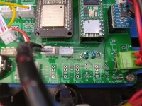
It's possible at this location because the trace is very small and all the 5V sense of all PCB component come here .
But why it's never append to me .Maybe because i never populate BUZZER and 3.3V led, but all other components are in use (GPS, RFID etc...)
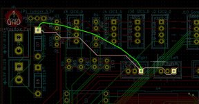
Simply try to solder a small wire between the connector J13 and the D7 out to replace the trace.
Certainly it explain also the trouble with perimeter.
Can you send a picture of the coil receiver
It's possible at this location because the trace is very small and all the 5V sense of all PCB component come here .
But why it's never append to me .Maybe because i never populate BUZZER and 3.3V led, but all other components are in use (GPS, RFID etc...)
Simply try to solder a small wire between the connector J13 and the D7 out to replace the trace.
Certainly it explain also the trouble with perimeter.
Can you send a picture of the coil receiver
Attachments
I just can't explain why everything works on your mowers, but something keeps breaking on mine.
I know I have no idea about electronics, but that bad?")
The 5V conductor path is also a little unfortunate, it first goes to all the connections and then to the Teensy and ESP.
In the new version I have connected the 5V directly to the Teensy, then to the ESP32 and only then to the connections. And trace is bigger.
There are also two capacitors to smooth out/stabilise the voltage.
I'll finish the new MainPCB this week and then order it, so I won't be bothered with it any more.
StefanH would also like to have circuit boards.
I know I have no idea about electronics, but that bad?
The 5V conductor path is also a little unfortunate, it first goes to all the connections and then to the Teensy and ESP.
In the new version I have connected the 5V directly to the Teensy, then to the ESP32 and only then to the connections. And trace is bigger.
There are also two capacitors to smooth out/stabilise the voltage.
I'll finish the new MainPCB this week and then order it, so I won't be bothered with it any more.
StefanH would also like to have circuit boards.
So the new MainPCB is installed and works so far. I haven't noticed any problems yet.
However, I still have the same problems as before. When I calibrate the motor, it runs for an extremely long time and apparently no revolutions are counted, at least nothing is displayed in the PFOD app. In the ODO test, however, I can see the revolutions and that fits so far.
When I start it in auto mode, it only moves a few centimetres and then turns as if there is an obstacle.
I suspect that the perimeter receiver is not working properly, so I will replace it.
@Bernard which version of the MainPCB board do you use for your new mower?
For power pcb:
I always use the same version V1.06 with small workaround in the latest soldering one
And never never never invert + and - because it's simple PCB ,so no security over over-voltage or polarity inversion
1 Use mow2 connector if only 1 mow motor to avoid small trace.
2 Put a small radiator on the battery mosfet
3 replace the big fuse by smaller polyfuse 5A


For main PCB it's the 1.01 with the resistor workaround.

Here the today first test video , at the end you can see the 2 PCB fully connected.
Stay to connect the bumper, emergency and start button and it's finish
I always use the same version V1.06 with small workaround in the latest soldering one
And never never never invert + and -
because it's simple PCB ,so no security over over-voltage or polarity inversion1 Use mow2 connector if only 1 mow motor to avoid small trace.
2 Put a small radiator on the battery mosfet
3 replace the big fuse by smaller polyfuse 5A
For main PCB it's the 1.01 with the resistor workaround.
Here the today first test video , at the end you can see the 2 PCB fully connected.
Stay to connect the bumper, emergency and start button and it's finish

So wie hier zu sehen, noch mit alten Motortreibern:

Ich habe aber eine größere Batterie und deshalb den Halter für die Motortreiber nicht verwendet.
Wenn du einen 3D Drucker hast, findest du dort die STL Dateien:
Ich habe aber eine größere Batterie und deshalb den Halter für die Motortreiber nicht verwendet.
Wenn du einen 3D Drucker hast, findest du dort die STL Dateien:
Matrix MOW800 PCB Holder
I have printed the PCB holder, it looks good. I'm testing an holder with rubber dampers. And just an other idea... I will test it: to tilt the power board for more access, better cooling and more distance from cover.
www.diy-robot-lawn-mower.com
SefanH
Well-known member
Habe keinen 3D Drucker, aber im Notfall kennt man ja immer einen.
Ich habe es ähnlich gemacht. Eine Befestigung der Motortreiber muss ich noch basteln, der Rest sitzt dank Heißkleber und Kunststoffbuchsen. Wo platziert man am besten den oder die Perimeter Empfänger? Klappt das im Gehäuse?

Ich habe es ähnlich gemacht. Eine Befestigung der Motortreiber muss ich noch basteln, der Rest sitzt dank Heißkleber und Kunststoffbuchsen. Wo platziert man am besten den oder die Perimeter Empfänger? Klappt das im Gehäuse?
Normaly with the last code version the receiver can work inside the platform , but only a test can confirm.Habe keinen 3D Drucker, aber im Notfall kennt man ja immer einen.
Ich habe es ähnlich gemacht. Eine Befestigung der Motortreiber muss ich noch basteln, der Rest sitzt dank Heißkleber und Kunststoffbuchsen. Wo platziert man am besten den oder die Perimeter Empfänger? Klappt das im Gehäuse?
View attachment 633
You can now use the 2 (right and left) to have a faster random mowing, tracking use the right one to follow the wire, so you need to adjust charging station location on wire according this.
Now that my mower is running again with a new PowerPCB (small), the shutdown is not working again. But it could be that I have broken it because I have bridged the start button with a jumper all the time when I was testing it
@Bernard
But I have another problem, sometimes a wheel keeps turning slowly, although it should actually stop. But this doesn't always happen, when I press stop in the odometry test in the Pfod app, it stops.
Could this be due to a setting or is the motor driver not working properly?
@Bernard
But I have another problem, sometimes a wheel keeps turning slowly, although it should actually stop. But this doesn't always happen, when I press stop in the odometry test in the Pfod app, it stops.
Could this be due to a setting or is the motor driver not working properly?
Yes This change disable the software shutdown.the start button with a jumper all the time
But I have another problem, sometimes a wheel keeps turning slowly, although it should actually stop. But this doesn't always happen, when I press stop in the odometry test in the Pfod app, it stops.
Can you explain , i don't understand when this append ??Could this be due to a setting or is the motor driver not working properly?
Yes, the bridge starts the mower immediately, but it now also does this when I have not connected anything to the start button. Unfortunately, I forgot to test this beforehand.
I may have broken Q4 by leaving it bridged the whole time.
But I don't feel like dealing with it at the moment, the mower has to run again first.
When I drive 3 meters in the odometry test, it sometimes happens that the left motor stops after 3 meters but the right motor continues to turn slowly. Only when I press Stop in the app does the other motor also stop. However, this sometimes also happens with the other tests in the odometry menu.
I have also observed this on the lawn, where it starts to turn in circles.
However, I suspect it is due to the motor driver or perhaps the motor, as it is always the same motor.