Matrix MOW800 PCB Holder

LaurentS

Well-known member
I have printed the PCB holder, it looks good.
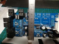
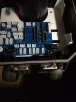
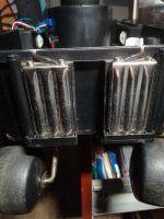
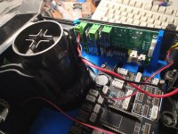
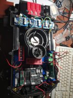
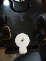
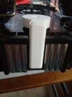
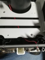
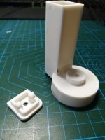
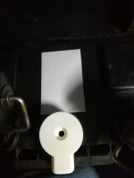
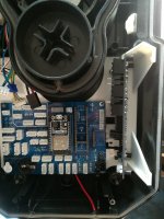
I'm testing an holder with rubber dampers. And just an other idea... I will test it: to tilt the power board for more access, better cooling and more distance from cover.
 

Attachments

  • IMG_20220129_121532_BURST001_COVER.jpg
    IMG_20220129_121532_BURST001_COVER.jpg
    718.1 KB · Views: 25
Last edited:
And just an other idea... I will test it: to tilt the power board for more access, better cooling and more distance from cover.
Bad idea, if we add connectors on the PCB we don't have enough place in this case; I stay on my last version with dampers.
In all cases I have to change my connectors, they are too high, they don't have to be higher than the PCB
 
Last edited:
I hope for you that PCB don't make high EMF noise on the receiver coil.
it 's better to first test the perimeter receiver signal before fix all the component in the chassis.
Sometime moving a wire for 2 cm can change the noise in the coil !!
 
You are certainly right, but unfortunately the housing is not a miracle of space.
Maybe the receiver can be placed a little further out from the bottom, but it will definitely be under the PCB.
But I wonder how other manufacturers do it? The receivers usually sit on top of the PCB?
 
Did you have a Photo?
If I measured correctly, we have 68mm from 3Dprint base to under the cover. With our connectors, we have 70mm. To be sure to have enough place under the cover, it would be better to weld directly on the PCB for J4, J6, J7, J9 and J10. Connectors can be added on wires if needed.
 

Attachments

  • IMG_20220129_204839_resized_20220129_084917240.jpg
    IMG_20220129_204839_resized_20220129_084917240.jpg
    596.6 KB · Views: 19
I hope for you that PCB don't make high EMF noise on the receiver coil.
it 's better to first test the perimeter receiver signal before fix all the component in the chassis.
Sometime moving a wire for 2 cm can change the noise in the coil !!
I've seen a video from you about this signal, if I'm right... I will watch this. I think about fixing the coil out of the housing... if it's possible to do this... the sensor out and the print card in the housing... .

Video from MegaBernard :D
 
Last edited:
I thought about installing the sensor at the bottom/between the loading padds.
 

Attachments

  • IMG_20220129_212238_resized_20220129_092251666.jpg
    IMG_20220129_212238_resized_20220129_092251666.jpg
    421.4 KB · Views: 15
  • IMG_20220129_212407_resized_20220129_092426431.jpg
    IMG_20220129_212407_resized_20220129_092426431.jpg
    684.5 KB · Views: 17
OK.
Maybe you can use the vertical box from my robomow with minor change.
 

Attachments

  • receiver box.zip
    665.2 KB · Views: 9
Inside Arduremote Test ODO menu you have the Peri Mag/Noise value.
Noise need to be the minimum when you test the wheel.
According to video Try to put DC/DC 24/5V far from coil
 
I was lucky and soldered the right two the wrong way round. The left one fits the height.
 

Attachments

  • IMG_20220130_141518.jpg
    IMG_20220130_141518.jpg
    861.3 KB · Views: 19
Rather narrow

@LaurentS Did you test if the USB Cable fit in the Teensy? the way i have the pcb in it does not fit
 

Attachments

  • IMG_20220130_144627.jpg
    IMG_20220130_144627.jpg
    919.5 KB · Views: 38
Last edited:
OK.
Maybe you can use the vertical box from my robomow with minor change.
Thanks Bernard, yes, perfect with minor change: for Mow800, with the possibility to bore a 6mm hole in the center to fix it.
 

Attachments

  • IMG_20220131_095709_resized_20220131_095950172.jpg
    IMG_20220131_095709_resized_20220131_095950172.jpg
    480.2 KB · Views: 18
  • IMG_20220131_095755_resized_20220131_095949480.jpg
    IMG_20220131_095755_resized_20220131_095949480.jpg
    436.4 KB · Views: 17
  • IMG_20220131_095855_resized_20220131_095948831.jpg
    IMG_20220131_095855_resized_20220131_095948831.jpg
    516 KB · Views: 17
  • Receiver box for Mow800 v7 v2.zip
    1.1 MB · Views: 6
Side screws for cover can't be installed; not enough place for thoseones, but it fits so nicely that I think I will glue it in place after the PCB resistor has been adjusted and the condensator has been bridged.
 

Attachments

  • IMG_20220131_102904_resized_20220131_102925893.jpg
    IMG_20220131_102904_resized_20220131_102925893.jpg
    831.4 KB · Views: 18
I will add a box for the Pn5180 NFC RFID on the back; the wires will go through the previous 6mm hole and the box will be screwed on other points. It will be one piece for both sensors.
 

Attachments

  • IMG_20220201_192751_resized_20220201_072815879.jpg
    IMG_20220201_192751_resized_20220201_072815879.jpg
    295.7 KB · Views: 21
Last edited:
Back
Top