First Design Perimeter Sender

Sascha

Administrator
Staff member
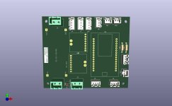
I've started designing a PCB for the perimeter transmitter, unfortunately I haven't been able to find a template for the INA3321 yet, which is kind of dumb.
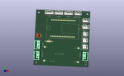
Maybe I will find one.
The motor driver would also have to be wired separately if you use the L298H.
But maybe an optocoupler instead of a motor driver would work?
 

Attachments

  • sender_V1.00.jpg
    sender_V1.00.jpg
    58.2 KB · Views: 22
  • sender_V1.00.pdf
    58.8 KB · Views: 10
Are you sure it's good to put INA3221 on the PCB.
In fact i use the ina3221 since 2 or 3 year, but normaly it's 26V max and the charger is 29.4V !!!!!
So maybe 2 INA226 are better.
If i can open your repo ,i try to show you what i want to say
 
I haven't taken it any further, my Zigbee network is pissing me off at the moment.
I read that the INA3221 can only handle 26V.
The INA226 is needed for the PowerPCB anyway, so you can use it at the same time. Fewer different parts -> simpler, I think
 
I am not sure it's a good idea to put the sender pcb inside the station.
It's directly on the floor and always under water and moisture. Many station on commercial mower have trouble with that feature (often slug escargot make shortcut on PCB)

I agree for 2 ina226 to replace the ina3221.

I read that the INA3221 can only handle 26V.
Me too, but work well since at least 3 years 24h/24 at 29.4V
 
I have the transmitter in the small simple case from the ardumower-projekt and not directly on the floor, but on small feet. No problems since 2 years.

Isn't there a voltage divider for the light sensor missing?
 
Yes, if you want to take the naked LDR, there is still something missing. But there are ready-made boards with LDR.
 
Regarding the LEDs, I thought of the following based on the original Matrix Station LED's:

- Power LED (normal red LED):
Power on with perimeter cable -> Lights up
Power on without perimeter cable or broken -> Flashing

- 3 Legs LED (DUO LED)
Mower in station charging -> flashes green
Mower in station IDLE -> lights green
 
New Layout Dimensions 10.2cm x 7.2cm.
The motor driver comes separately, so it is not included on the PCB
And the 3 Pin Socket LED is still missing
 

Attachments

  • sender_V1.00.jpg
    sender_V1.00.jpg
    70.3 KB · Views: 16
  • sender_V1.00.pdf
    66.6 KB · Views: 4
Slightly revised and the RED/GREEN LED added.
@Bernard is it correct that the INA is connected before the DC/DC converter?
 

Attachments

  • sender_V1.00.pdf
    71.3 KB · Views: 6
Using INA3221 it's normal because you only have 1 input and the same voltage on the 3 outputs,
But with INA226 or INA219 you can connect U1 at the output of the DC/DC1, by this way it's also possible to know the voltage in the perimeter wire. (y)
ESP32 Vin is not connected like in my wiring (i use the 5V output of the motor driver L298N to power the ESP32.). You can test your way but if DC/DC out >12V you can burn the ESP32.
 
Für die Power-Led ziehst Du ca. 15mA aus dem Spannungswandler des esp (3,3V / 220 Ohm). Das erscheint mir ungesund, da mit max. 12V an esp-Vin der Spannungsabfall am Wandler ca 9V ist -> 9V*15mA !? Sehe ich das richtig ? Hier ist auf jeden Fall der maximal zulässige Strom an Allen Pins des esp zu beachten. (und der unterscheidet sich noch nach 1: Entnahme vom Wandler -> Pins als Ausgang, also 3,3V gegen Außenpotential und 2. Ableitung gegen Masse -> also Pins als Eingang gegen Masse geschaltet. Hier ist der max Strom höher).
 
You are right @Bernard , I misinterpreted your circuit. I will change it.

@Fürst Ruprecht
Da bin ich nach den üblichen ESP32 LED Tutorials vorgegangen, die haben alle einen 220 Ohm Widerstand eingezeichnet.
Was schlägst du da vor?
 
1.Ich würde einen kleinen 3,3V DC/DC-Wandler einsetzen, der den esp und den Rest versorgt.
2.Die Led würde ich an 3,3V hängen und vom esp nach Masse schalten. ( in diesem Fall wird nur die Transistorstufe belastet und nicht der Spannungswandler) Grundsätzlich sollten die Esp-Pins besser nicht speißen.
Daß man den esp an eine Vin größer als 5V hängt ist mir neu, was aber nichts heißen muß.
Ich bin bisher davon ausgegangen, daß aufgrund des USB-Anschlusses der Wandler lediglich von 5 auf 3.3V reduziert.
Ansonsten muß im Zweifelsfall ein Transistor zwischen esp und zu schaltender Last eingefügt werden.
 
Der ESP32 kann mit bis zu 12V betrieben werden, ob das gesund ist oder nicht, sei mal dahin gestellt. Der Spannungswandler wird dabei sehr warm.
 
Im Datenblatt des esp32 steht:
I(OH) = IO-Pin-High: 20mA
For VDD_SDIO power domain, per-pin current sourced in the same domain is gradually reduced from around 30 mA to
around 10 mA, VOH >=2.64 V, as the number of current-source pins increases.
I(OL) = IO-Pin-Low: 28mA
Im Netz wird auch bestätigt, daß der Spannungswandler auf den esp-Modulen lediglich dafür ausgelegt ist, von 5V USB auf den internen 3,3V-Bedarf zu regeln.
 
So I have now revised the board again, if there are no comments I will route it like this.
A few pin labels are still missing.
 

Attachments

  • sender_V1.00.jpg
    sender_V1.00.jpg
    63.4 KB · Views: 11
  • sender_V1.00.pdf
    72.6 KB · Views: 6
Wie steuerst du denn das Perimetersignal an? Für den ESP eine extra Spannungsversorgung? Man kann doch auch nach dem DC/DC-Wandler einen Festspannungsregler verbauen.
 
Der DC/DC Wandler ist für das Perimeter Kabel, die 5v müssen vom Motortreiber kommen, der nicht mit auf die Platine kommt.
Hast du einen Link zum Festspannungsregler?
 
It's OK.
Maybe you can name J4 as screen.
Double check the DC/DC footprint to be sure.
 
Back
Top