Converting an Ambrogio L210 to GPS RTK

tgcoder

Member
I started working on converting my L210 to use RTK. I already have several other mowers, including an L32, 4.00 Elite, and 4.36 Elite. I don't like them mostly due to the track they make around their mowing areas. I purchased the L210 used, so that I could use it as a test machine to convert to RTK. So far I have built a station to transmit the error correction data and placed it central to the property. I have 6.5 acres of land and about 5 acres is mowable. I have also built a device that I used to plot GPS data every 12" around my test area, which encompasses about .46 acres. It plots the latitude and longitude into a file which I will use to control the test mower.

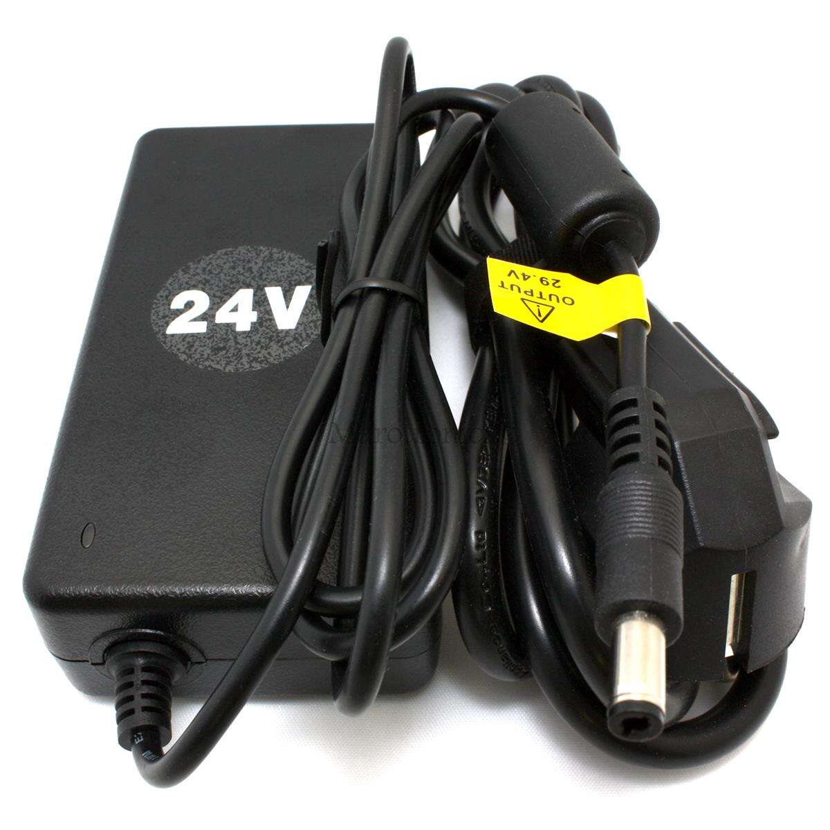
Now, I am starting on modifying the mower itself. As I am building all of the circuits myself, my first problem is to devise a charger circuit for the mower. It contains a 26v lithium battery. I was wondering if anyone had a circuit source I could copy. The charging station seems to only supply a source for the power. The charging circuit appears to be on the robot's mother board. Can anyone help?
 
If you use lithium cells you need a charge manager that controls the charge current. therefore, ready-made, encapsulated chargers are often used. an alternative are the battery management systems, which regulate the charging current and charge all cells evenly. they can be used with a suitable DC voltage source. The "Ardumower" perimeter transmitter uses a suitable lithium charger and switches between perimeter wire and charging mode.
 
The mower has a single 25.2 volt battery. I was able to find the specs on a similar battery made by a different manufacturer. However, I'm sure the specs are the same for both batteries. Using that info, I can design a charging circuit for it if needed. My problem is that I'm not sure if the motherboard on the current mower contains a charger or just battery monitoring cirduit so that it can determine when to return to the charging station. I would think that the charging station knows how to charge the battery, but I'm not sure about that yet. Thanks for your reply.
 
The mower has a single 25.2 volt battery. I was able to find the specs on a similar battery made by a different manufacturer. However, I'm sure the specs are the same for both batteries. Using that info, I can design a charging circuit for it if needed. My problem is that I'm not sure if the motherboard on the current mower contains a charger or just battery monitoring cirduit so that it can determine when to return to the charging station. I would think that the charging station knows how to charge the battery, but I'm not sure about that yet. Thanks for your reply.
On mower :
Power PCB read in real time the Bat voltage and the charging sense using INA226
On Sender :
Esp32 also read the charging sense using INA3221

Software charging manage the bat voltage by this way.
On mower:
A low voltage (23V for example) tell mower it's time to return to charging station.
When mower is in charge a low charging sense (0.2Amp for example) can stop the charging process ,or a duration limit (5 hour in hard code).
It's a good process for lead Acid ,but for a perfect Li-Ion charging process it's better to use a true li-ion charger with variable sense connected to sender.
On sender:
When mower touch the charging contact signal wire is stop and charger is use to fill the mower battery.

Wiki for software:

sample of li-ion 7S charger (7*4.2V=29.4V at full charge) . your 25.2V is the nominal value of the battery (7*3.6V=25.2V)
 
Thanks for the reply. For some reason, I never considered replacing the charger in the charging station. Your selection would seem to work perfectly, and the cost is very reasonable too.
 
If anyone is interested, I used a UMLIFE Three-Phase DC Brushless Motor Controller that I got from Amazon to test with my L210 in order to control the motors. It worked nicely with a potentiometer and using PCM. The wiring connection I used was:
Motor
MA - Black
MB - Red
MC - Brown

For the Hall Sensor wiring:

5v - Red
Ha - Green
Hb - Yellow
Hc - Blue
Gnd - Black

For PCM, use the control input for the PCM signal and ground to ground. Make sure the onboard pot is set to minimum or fully counter clockwise.
 
Thats the X11H driver i use too.
If there is not enough space in the mower, a smaller driver (X12H) is presented here by Bernard.
 
I've got plenty of room for a 210mm x 100mm board, which will easily fit three of them plus all of my other parts.
 
This is version 3.0 of my PCB that I've been working on. The RTK module resides on top of the robot along with an accelerometer and magnetic module. I still have lots of wiring to do. The PCB fits nicely where the previous board was.
 

Attachments

  • IMG_20230305_162917822.jpg
    IMG_20230305_162917822.jpg
    262.1 KB · Views: 13
That will come later. I had to build it so that it would fit where the old circuit board was. Also, I just wanted to make something that I can program to work for now. The bells and whistles will come later. BTW, there is circuitry underneath the drive modules.
 
Back
Top