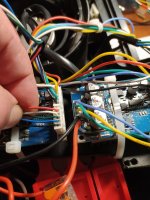
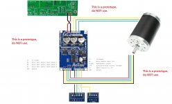
I have make some Pictures, how i have connected the Matrix MOW Motors to the Brushless Controller.
+5V --> 5V OUTPUT normally not needed
EL <-- Enable/Disable HIGH=Enable/LOW=Disable -> Testing with mine it is swapped
ZF <-- Direction HIGH=Forward/GND=Backwards
VR <-- Analog 0..5V (PWM)
GND <--> GND
SIGNAL --> Odometry
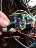
Cable assignment mower motor:
White - A
Green - B
Blue - C
First Picture: Motor Phases Drive Motor
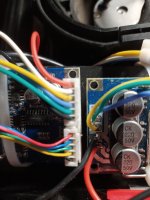
Second Picture: Hall Sensors and Signal, GND, 5V OUT
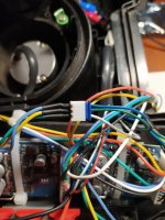
Third Picture: Motor Phases MOW Motor
+5V --> 5V OUTPUT normally not needed
EL <-- Enable/Disable HIGH=Enable/LOW=Disable -> Testing with mine it is swapped
ZF <-- Direction HIGH=Forward/GND=Backwards
VR <-- Analog 0..5V (PWM)
GND <--> GND
SIGNAL --> Odometry
Cable assignment mower motor:
White - A
Green - B
Blue - C
First Picture: Motor Phases Drive Motor
Second Picture: Hall Sensors and Signal, GND, 5V OUT
Third Picture: Motor Phases MOW Motor
Attachments
Last edited:
")


 ok I will go really small step by small step... .
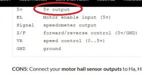
")