RL2000 goes Teensy

Boesling

Active member
Hello everyone,
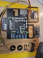
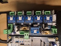
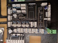
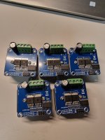
Now that I have all the parts together and the circuit boards are soldered, it's time to mount them in the chassis of the RL2000. Many thanks at this point to Sascha for the circuit boards and to Bernard for the 3D data. :)
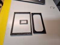
@Bernard Do you have any pictures and hints how to mount the Odo inside the RL2000? As I know, it is needed to dismantle the gear.
Some time ago I read that you should open a wire on the Teeny board to be able to programme it when it is installed. Unfortunately, I can no longer find the thread.

Now I go ahead by preparing all the connection cables.
All further information is very welcome. :love:

Daniel
 

Attachments

  • 20231210_181205.jpg
    20231210_181205.jpg
    1.3 MB · Views: 20
  • 20231210_181220.jpg
    20231210_181220.jpg
    1.2 MB · Views: 20
  • 20231210_181225.jpg
    20231210_181225.jpg
    1.3 MB · Views: 18
  • 20231210_181306.jpg
    20231210_181306.jpg
    572.9 KB · Views: 11
  • 20231210_182428.jpg
    20231210_182428.jpg
    967.1 KB · Views: 9
Some time ago I read that you should open a wire on the Teeny board to be able to programme it when it is installed. Unfortunately, I can no longer find the thread.

Yes you need to cut a shunt at back on teensy to avoid that it is powered by the mower battery AND at the same time by the USB cable from PC.
pad to cut.png


For odometry you need to disassemble the gearbox and add the 3D part with magnet (don't forget to put magnet correctly N S N S N S etc ...
Disk is clip on the original magnet (remove the 2 small original magnet) and 1 point of hot glue is add to fix everything.
You have on the gear box some Thin washer and you can use then at correct location to avoid that Odo disk don't touch the gear.

For coil receiver you can test to put then directly inside the chassis

20201013_180513.jpg20201013_181317.jpgmagnet odo.jpg
View attachment odo magnet.mp4
 
Hello I just saw this post, my question is what kind of für Neodym magnet it is and where can I buy it (Amazon i think). It is an alternative to my optokppler Encoder, so many thanks in advance
 
Hello I just saw this post, my question is what kind of für Neodym magnet it is and where can I buy it (Amazon i think). It is an alternative to my optokppler Encoder, so many thanks in advance
I ordered it here
The 3d-file for the disc is designed by @Bernard
 
Thanks , so if I count right there are 34 of them in the encoder blade.
i Ordered just by amazon. It is a great solution. I did it with bigger magnets before, but on a wheel with 9cm diamter, the magnetic field was to strong. So no day without learning.
 
Short update from my side: The PCBs are mounted and the first checks are done.
All 6 INAs were found by I2C-Scanner, and I can upload the teensymower firmware to the teensy.
But unfortunately I get no serial monitor output if I start the teensy. The buzzer is working for a while with 2 different sounds.
I'm using VS code with platformIO and with other firmware the monitor works fine (e.g. I2C scanner).
Is it needed to hv the ESP installed on the PCB to get the serial monitor?
Thanks @ all ☺️
2024-01-0916.01.425158660628214964332.jpg
 
The serial monitor should also work without ESP.
If you only connect the Teensy to the computer, does the Serial Monitor work?

Have you already disconnected the two contacts on the back of the Teensy?
Unfortunately I can't find the article by Bernard where there is a picture showing which contacts have to be disconnected, after which the Teensy can be connected to the PC, but needs the power supply from the PCB.
 
Short update from my side: The PCBs are mounted and the first checks are done.
All 6 INAs were found by I2C-Scanner, and I can upload the teensymower firmware to the teensy.
But unfortunately I get no serial monitor output if I start the teensy. The buzzer is working for a while with 2 different sounds.
I'm using VS code with platformIO and with other firmware the monitor works fine (e.g. I2C scanner).
Is it needed to hv the ESP installed on the PCB to get the serial monitor?
Thanks @ all ☺️
View attachment 1133
If teensy is powered by battery ,you need to cut the trace at back:

Can you test with arduino ide console ?

But without ESP32 certainly teensy hang on boot and nothing is present into console.
ESP32 is mandatory to first initialise the ram:

Also IMU is mandatory on start to have a correct I2C working mode

//On the first start if beep on error you need to do:
//command/off
//factory setting and DO NOT save setting.
//reboot
//command/off
// clear error counter
//setting save user setting.
//redo the motor calibration.
 
The serial monitor should also work without ESP.
If you only connect the Teensy to the computer, does the Serial Monitor work?

Have you already disconnected the two contacts on the back of the Teensy?
Unfortunately I can't find the article by Bernard where there is a picture showing which contacts have to be disconnected, after which the Teensy can be connected to the PC, but needs the power supply from the PCB.
Thanks for your reply.
I have already disconnected the two contacts on the back and I'm able to program the Teensy while it is plugged onto the Main PCB.
If teensy is powered by battery ,you need to cut the trace at back:

Can you test with arduino ide console ?

But without ESP32 certainly teensy hang on boot and nothing is present into console.
ESP32 is mandatory to first initialise the ram:

Also IMU is mandatory on start to have a correct I2C working mode
@Sascha @Bernard many thanks for your reply.
I have already disconnected the two contacts on the back and I'm able to program the Teensy while it is plugged onto the Main PCB.
So I will program the ESP and plug it and the IMU on the Main PCB first.
If it still not work ,I will try the Arduino IDE.
Thank you all :)
 
Short update from my side.
I'm working on all the mechanical things and during the disassembling of the gear box I found out that all the bearings are gone. So I've ordered new ones for that.
I also bought a LiFePo4 battery with 24V and 6Ah, hope this will be good enough for ma case.
@Bernard
How did you remove the 2 weights in the front of the mower? Is there any trick?
The bumpers at the back are not used,or?
Thanks to all of you.
 
Hi all,
I've finished my mechanical work on the mower, did the basic wiring and start trying the drive-motors first.
20240316_183626.jpg

I started with Teensyber 1.483 from @Bernard 's GitHub and TeensymowerWebControl for ESP32. I used PlatformIO for compiling and uploading the firmwares and it works, so far.
Now I started the Odo-Test from the Webinterface and the motors are jumping back and forward and I have no idea why. Also the Odo-Counter for the left wheel counts negative numbers.

Odo_Test.png

C++:
#if defined (RL2000)  // here all setting for YARDFORCE
//*****************possible list of motor driver set to :****************
// 1 for brushless ZS-X11H v1 Driver
// 2 for DC L298N Driver
// 3 for DC BTS7960 Driver
#define LEFT_MOTOR_DRIVER 3  //never mix BL and DC on drive motor
#define RIGHT_MOTOR_DRIVER 3
#define MOW_MOTOR_DRIVER 3

#define BUMPER_IS_SWITCH true  // set to true if the bumper is a single ON/OFF switch
#define BUMPER_REAR_EXIST false  // set to true to manage the rear bumper connected on CAN3 J20 connector
#define BUMPER_ARE_NORMALY_CLOSED false  // set to true if the bumper contact is closed when nothing is hit

#define START_BUTTON_IS_NC false //if button is normaly closed

// mower can have a cover that stop the mowing cycle but power still on the PCB,mower only start after closing the cover
// start button is under cover , so after push the start button you have 10 seconde to close cover and mower start
// openning the cover stop mowing cycle
#define MOWER_HAVE_SECURITY_COVER false // mower can have a cover that stop the mowing cycle but power still on the PCB,mower only start after closing the cover

#define INA226_MOW2_PRESENT true
#define INA226_MOW3_PRESENT true

#define ODOMETRY_ONLY_RISING false
#endif


#define PWM_FREQUENCY_ZSX11HV1  20000 //
#define PWM_FREQUENCY_L298N  10000
#define PWM_FREQUENCY_BTS7960  10000


Code:
Save Stats Adress Start = 800.00 Stop = 826.00
WAIT / OFF
Log Filename : 2403161828.txt
Save Stats Adress Start = 800.00 Stop = 826.00
STATION / STAT
TESTING / TESTMOTOR
Warning : IMU Roll / Tilt -- > -9.00 / 60.00
Motor mow STOP start again after 1 minute
TESTING / STOPONBUMPER
TESTING / BUMPREV
TESTING / LANEROL1
Bumper left trigger
TESTING / STOPONBUMPER
TESTING / BUMPREV
TESTING / LANEROL1
Bumper left trigger
TESTING / STOPONBUMPER
TESTING / BUMPREV
TESTING / LANEROL1
Bumper left trigger

The serial console shows a lot of messages "Bumper left trigger", but the bumpers are not connected.
Could this be the reason for the motors behaviour?

Thanks for your help :)
 
Into mower.h line 18 to 23
Code:
//**************************************************************
// ------- select one platform type -------------------
//**************************************************************
//#define MI632
//#define YARDFORCE
#define RL2000
//#define MOW800

you need to select RL2000 platform.
Tell me if you don't forget this setting ?
 
Into mower.cpp try to change the factory setting for RL2000:
Code:
#if defined (RL2000)
  name = "RL2000"; //Set the Name of platform
  // ------- wheel motors -----------------------------
  motorRightSwapDir     = false;    // inverse right motor direction?
  motorLeftSwapDir      = true;    // inverse left motor direction?
  motorPowerMax     = 50;    // motor wheel max power (Watt)
  bumperUse         = 0;      // has bumpers?
  perimeterUse       = 0;      // use perimeter?
  imuUse            = 0;       // use IMU?
#endif
Do a factory setting by this way.
//On the first start if beep on error you need to do:
//command/off
//factory setting and DO NOT save setting.
//reboot
//command/off
// clear error counter
//setting save user setting.

Using arduino serial monitor or the one from VS code send us a copy of your setting :
i don't remember exactly, but Send d and x i think.
 
@Bernard this did the trick so far.
I use Arduino IDE now,recompiled all, upload and apply the factory settings.
Now the drive motors works as expected.

Next steps are the mower motors and the bumpers.
Thanks @Bernard
 
Back
Top