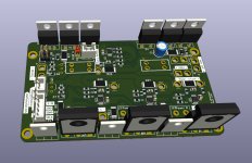
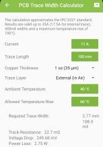
Based on:

 github.com
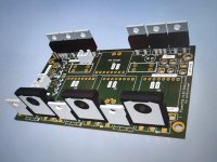
Version for Landrumower and Teensy (different file in attachement).
To do:
-UNTESTED!!!!
-Replace components for LSCS versions to be SMT machine assembled.
Because the components stock can change in time in lcsc warehouse. The production file should really be done, before sending file for production:
The easy way is to assign lcsc components id in scheme (that are currently in stock). And use the Kicad plugin (using plugin manager) to generate all files:

 github.com
Differences:
-one version rewired to be compatible with Landrumower scheme.
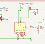
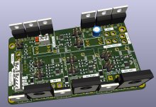
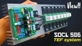
-repositioned mosfets/diodes for easy integration with heatsink:
-smaller PCB size (lower manufacturing costs).
Quote for PCB:
Power_PCB_v100small - 33.24 usd
Power_PCB_v100small_MOD - 5 usd
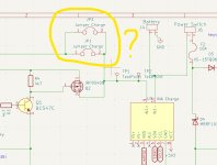
-added optional safety braking resistor circuit for BLDC driver especially for MOW motor.
It can be skipped if not necessary.
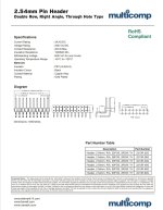
-added xt-30 connectors for high current.
-added holder for Car blade fuses. (That fuse can't be Polyfuse for safety reason).

 electronics.stackexchange.com
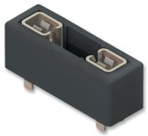
Or External Panel Mount Fuse Holder

-Upgraded diodes for 100V. 45V is not enough.
-added diodes for switching Mosfets. In case of Mosfet failure, it should not fry Raspberry port.
TeensyMower-PCBs/Power_PCB_v100small at main · Starsurfer78/TeensyMower-PCBs
PCB's Folder for Teensy 4.1 based Robot Lawn Mower - Starsurfer78/TeensyMower-PCBs

Version for Landrumower and Teensy (different file in attachement).
To do:
-UNTESTED!!!!
-Replace components for LSCS versions to be SMT machine assembled.
Because the components stock can change in time in lcsc warehouse. The production file should really be done, before sending file for production:
The easy way is to assign lcsc components id in scheme (that are currently in stock). And use the Kicad plugin (using plugin manager) to generate all files:
GitHub - bennymeg/Fabrication-Toolkit: An JLC PCB Fabrication Plugin for KiCad
An JLC PCB Fabrication Plugin for KiCad . Contribute to bennymeg/Fabrication-Toolkit development by creating an account on GitHub.
Differences:
-one version rewired to be compatible with Landrumower scheme.

-repositioned mosfets/diodes for easy integration with heatsink:

-smaller PCB size (lower manufacturing costs).
Quote for PCB:
Power_PCB_v100small - 33.24 usd
Power_PCB_v100small_MOD - 5 usd
-added optional safety braking resistor circuit for BLDC driver especially for MOW motor.
It can be skipped if not necessary.
Why use?
(...) if you have a big mow motor with a lot of inertia ,the driver can send more than 100 V on it's 24V input if you directly brake it from full speed and destroy some component on the main PCB (not the driver one).
Normally you need a power resistor to absorb the power peak.Or a big capacitor(...)
 forum.roboteers.org
jyqd2021
(...)
This braking function was not yet available on the 2017 PCB. A slight disadvantage here is that the braking...
ZS-X11D1 (JYQD2021) Treiber und Sunray
Da es bereits einige User gibt, die positive Erfahrugnen mit dem oben genannte Treiber gemacht haben, wollte ich und @Algo hier unsere Erfahrungen für andere, die evtl. diesen Treiber einsetzten möchten, dokumentieren. Den Treiber gibt es aktuell in der Bucht mit und ohne Hall-Sensor-Eingängen...
forum.ardumower.de
(...) if you have a big mow motor with a lot of inertia ,the driver can send more than 100 V on it's 24V input if you directly brake it from full speed and destroy some component on the main PCB (not the driver one).
Normally you need a power resistor to absorb the power peak.Or a big capacitor(...)
Beiträge von Lars - German Roboteers Association e.V.
jyqd2021
(...)
This braking function was not yet available on the 2017 PCB. A slight disadvantage here is that the braking...
-added xt-30 connectors for high current.
-added holder for Car blade fuses. (That fuse can't be Polyfuse for safety reason).
How do I choose a fuse? Fusible Links vs Polyfuse?
I realise this is an extremely broad subject area but I need to know how to choose a fuse to protect a circuit. Recently, a cheap PSU of a friend's blew up quite spectacularly (the two primary MOS...

Or External Panel Mount Fuse Holder

-Upgraded diodes for 100V. 45V is not enough.
-added diodes for switching Mosfets. In case of Mosfet failure, it should not fry Raspberry port.
Attachments
Last edited:

