HowerMower

Paddy

Well-known member
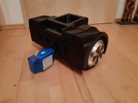
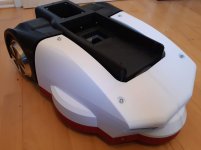
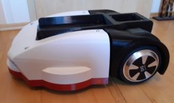
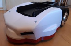
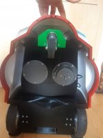
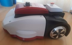
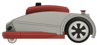
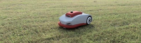
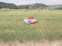
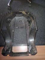
As I'm currently waiting for some components to continue with ROSMower, I started to build a 3D printable chassis from scratch. I call it HowerMower, as it is based on Hoverboard Motors, battery, PCB as motor driver and some other components of Hoverboard.
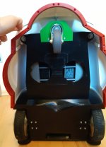
All motors operates at 42V, just because Hoverboards do so. But less voltage will also work.

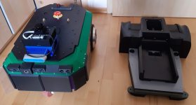
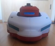
In my opinion, chassis and software should be exchangeable and not related to each other. That's the reason why I will distinct between HowerMower as Chassis and ROSMower as Software stack.

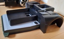
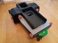
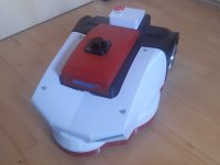
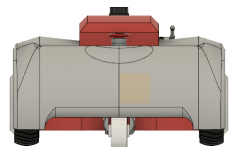
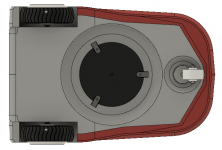
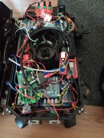
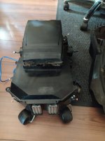
The upper box with antenna contains all expensive electronic parts, like RaspberryPI or Jetson Nano, Lidar, Stereo Camera and so. It will be detachable so it can be carried to a different robot. As the Ardumower PCB will fit inside, it would be also possible to use it with nearly any PCB or Software you want.

For build instructions, 3D files and BOM, please visit https://hovermower.github.io

I'm interested what you think about this.
MowerAssembly_2021-Sep-15_09-26-11AM-000_CustomizedView53425415533.png
MowerAssembly_2021-Sep-15_09-29-06AM-000_CustomizedView210065667.pnginside.pngfront.pngright.png
 

Attachments

  • back.png
    back.png
    45.2 KB · Views: 10
  • bottom.png
    bottom.png
    103.4 KB · Views: 10
  • left.png
    left.png
    78.2 KB · Views: 12
  • MowerAssembly_2021-Sep-15_09-27-11AM-000_CustomizedView42430555591_jpg.jpg
    MowerAssembly_2021-Sep-15_09-27-11AM-000_CustomizedView42430555591_jpg.jpg
    306.9 KB · Views: 12
  • MowerAssembly_2021-Sep-15_09-30-21AM-000_CustomizedView12710442068.png
    MowerAssembly_2021-Sep-15_09-30-21AM-000_CustomizedView12710442068.png
    783.8 KB · Views: 12
Last edited:
Hi Paddy, that looks really interesting.
Is the upper part of the chassis oscillating so that it can be used as a bumper?
How big can the circuit board be that fits in there?
And how big is it overall?

I would split the chassis, a simple elongated housing for motors, PCB battery with a flat lid and a housing that goes over the top as a bumper.
 
My current Arctic Hare chassis acts as a bumper but it has drawbacks. It doesn't recognise the direction of an obstacle correctly, so it often turns wrong. Also it vibrates and make lot noise. And bumper gets triggered by high lawn, small bumps in lawn and by charging contacts. At the end, it collects dort.

So this will be a solid chassis instead where the red part will act as bumper. You can either attach Bumperduino tube. But it will also be possible to move like the bumper on Tianchen Chassis does. This is damned simple and works reliable.

The Main PCB Box is 280x150 outer dimension. The overall mower is approx 420mm width, 570mm length and 280mm height. Cutting height will be up to 80mm
 
I have noticed that my mower often bumps into the top (garden loungers, children's swings, climbing wall).
Since my housing serves completely as a bumper, this works quite well, maybe the rubber bumpers are too soft?
There should be enough space in the Mower
 
Which chassis do you use? I use an Arctic Hare chassis with a mod I did to get a moving body.
It is a fair point that it would be good to have this again. So after sketching around, here is a Version which might fit better.

Another drawback at the first design was it was unable to cut the edges. So now we can use a much larger disc or place the mower disc with some offset from the middle of the mower to one side. The gap between the moving front shell and the static back is 10mm. PCB Box itself doesn't move as it is fixed attached to the motor section.

floating_body_bottom.pngfloating_body_front.pngfloating_body_right.pngfloating_body_top.png
 
I used a Matrix Mow, but its hard to get all the Hardware into it.
 

Attachments

  • IMG_20210917_153347.jpg
    IMG_20210917_153347.jpg
    1.3 MB · Views: 17
  • IMG_20210917_153332.jpg
    IMG_20210917_153332.jpg
    487.4 KB · Views: 24
  • IMG_20210917_153320.jpg
    IMG_20210917_153320.jpg
    1.1 MB · Views: 24
  • IMG_20210917_153302.jpg
    IMG_20210917_153302.jpg
    692.8 KB · Views: 24
  • IMG_20210917_153245.jpg
    IMG_20210917_153245.jpg
    1.2 MB · Views: 24
Hello,

the last couple of days (or was it weeks?), I planned a new 3D printable chassis which fits to Hoverboard Motors. Some of the initial ideas you find in this thread. This is my 4th Mower project and in past, it was always a nightmare to build a proper documentation afterwards. So this time, I try to do it even better by creating documentation during build.

As statet earlier in this thread, I try to distinct chassis, electronics and firmware separately. So you can re-use the chassis only, if you want.
Because I don't want to use a forum to document the robot (we have seen forums raising and falling in past projects), I've build this page here


It will be my starting point for documentation. So if you're interesting in my progress, have a look there. But I will still update my progress here as well.

Current status: the first, five mayor parts has been printed with success. Only two main parts are missing to complete the inner chassis.
 
Hi Paddy,
did you have some picture from the Printed Parts?
I would love to see what they look like in real life :)
 
I recently updated the documentation repository. There you find some real pictures. I added a few here.
Yesterday, I assembled the rear rection. All parts fits perfect, Motors as well and there is lot of space left for battery and PCB. Fells like Christmas to me
 

Attachments

  • lower_chassis.jpg
    lower_chassis.jpg
    131.8 KB · Views: 26
  • Rear_section_complete.jpg
    Rear_section_complete.jpg
    150.3 KB · Views: 25
  • Comparsion_1.jpg
    Comparsion_1.jpg
    109 KB · Views: 25
It looks really great.
Can you say if a 7S3P battery (15x6x6cm) fits in there?
How long have you been printing now?
Another thing I noticed, the front upper case works as a bumper?
Maybe it would make sense to raise it so that it is flush with the red box on top?
If you bump into something with the red box, the bumper won't notice.
In any case, it's a really nice case.
 
Hello,

the battery I use is 10S2P with approx. 140x65x80mm and there is still plenty of space around. So yes, I think yours will fit as well.

The overall printing time until now was 127h in total. All parts of lower chassis (not the white bumper part) has been printed without any issue.
You're right, the white front cover acts as bumper. As I share all STL and SETP files, it will be an easy task to adjust all parts to your needs. For example, I'm not sure if the PCB box will need to be that high. But I don't care too much in bumping with this into as I use a LIDAR and a depth camera for collision avoidance.

Next steps will be preparing and print the front cover. It will consists out of three main parts. I need to add mounting flanges, cable guides and other things before I can start to print. But this will take some additional time as I will not be able to work much on this next week.
 
After vacation and some work the last couple of days, I made a huge progress in building hovermower.I've updated all repositories of chassis and want to share the current state with you.
 

Attachments

  • chassis_final_4.jpg
    chassis_final_4.jpg
    186.9 KB · Views: 20
  • chassis_final_3.jpg
    chassis_final_3.jpg
    241.5 KB · Views: 19
  • chassis_final_2.jpg
    chassis_final_2.jpg
    190.7 KB · Views: 20
  • chassis_final_1.jpg
    chassis_final_1.jpg
    174.4 KB · Views: 20
  • chassis_bottom.jpg
    chassis_bottom.jpg
    374.7 KB · Views: 19
  • lower_chassis_complete.jpg
    lower_chassis_complete.jpg
    163.1 KB · Views: 22
Hi @Paddy ,
can you put the link to your page in your first post, so it's easier to find?

For the charging contacts, are the two square holes in the front intended?
Another thing that just occurred to me is how far do the blades come up against the chassis?
 
The two larger cutouts are for additional sensors or LEDs. I plan to re-use the LED of Hoverboard (reuse as much as possible). They are really bright, it may look cool and maybe it helps the camera when mowing late evening. Maybe I'll add sonar later. It is not planned now but who knows. If they doesn't get used for anything, I'll print a small lid to close them.
For charging contact, two options are build in. First, the rear mounting screws of floating chassis part can be used as charging contacts. To do so, use brass screws. Underneath there are small holes to guide cables to this area especially for charging. But I'm not sure if it is a good place so I also added two 8mm holes in front nose. They are only partially "drilled" from inside and not visible from outside. To place charging contacts here, simply drill through the front nose and you're done.
There is a build-in cable guide to route cables up to 7mm from rear to front.

What do you mean with blades come up to chassis? Do you mean max height of lawn? It depends on your mowing disc but it is up to 70mm. I use a disc with 190mm diameter. Equipped with blades, the space between chassis and tip of blades is approx 27mm. It is more dangerous than commercial ones but this way, I can cut to the edge. But If you use smaller discs, it becomes safer and also you can add two mow motors and discs. With a large one like mine, only one fits.
 
What do you mean with blades come up to chassis? Do you mean max height of lawn? It depends on your mowing disc but it is up to 70mm. I use a disc with 190mm diameter. Equipped with blades, the space between chassis and tip of blades is approx 27mm. It is more dangerous than commercial ones but this way, I can cut to the edge. But If you use smaller discs, it becomes safer and also you can add two mow motors and discs. With a large one like mine, only one fits.
That's answer my question, thanks
 
Milestone reached.
HoverMower (name of 3D printed chassis) is complete now. Everything fits perfectly and is operational. You can equip it with any electronics you want, a PCB1.3 should also fit inside the PCB Box (red). As already explained, you can use a simple UART interface to control each motor. You'll get odometry data, current sense and others back. I tried to re-use as much as possible from Hoverboard. So I took motors, PCB, battery, chargercharger plug, button and even LED headlights.

ROSMower is a HoverMower operated with ROS, robot operating system It is also prepared for more interesting tasks now. Equipped with NVidia Jetson, LD06 Lidar, Intel Realsense D435 stereo depth camera, BNO085 IMU, lawn might be out of chances. For power monitoring (battery, charge, disconnect battery), control mow motor and to sense perimeter wire, a base controller (Arduino Nano) has been implemented.

Special Thanks Bernard and Sascha for providing me with the PowerPCB. It works good and I'm happy that I hadn't need to build this by my own.

Right now, ROSMower can be driven around by a PS4 bluetooth controller (teleop). Next step will be implementing RtabMap for mapping and localization.

As this project becomes even more complex, I've created a new Git organization named HoverMower (https://github.com/HoverMower). It contains repos for documentation, 3D filed (STL and STEP), base controller firmware, related ROS packages and so on. It is up to you to cherry-pick what ever you need.

Documentation can be found here (lots of documentation still missing) https://hovermower.github.io/
 

Attachments

  • 20220128_121225.jpg
    20220128_121225.jpg
    167.2 KB · Views: 14
  • 20220128_121208.jpg
    20220128_121208.jpg
    75 KB · Views: 13
  • 20220128_121151.jpg
    20220128_121151.jpg
    76.6 KB · Views: 14
  • 20220128_121148.jpg
    20220128_121148.jpg
    120.1 KB · Views: 14
  • 20220128_121141.jpg
    20220128_121141.jpg
    96.7 KB · Views: 19
Good work, I like it really, but I would make a few changes to the housing, as it might not be quite optimal for my area.
I will definitely keep an eye on this topic, as I find it quite interesting and maybe I will get my hands on a Hoverboard one day :)
 
Next Milestone reached. I had some hard times to get ROSMower up and running. It was easy to set up ROS to teleoperate the robot around. It was also easy to get Lidar and IMU working as well as my base controller, which acts for power management, perimeter and bumper.

But the Intel RealSense D435 stereo depth camera was really hard to get running. In general, they're easy to set up even with ROS but things become complicated with NVidia Jetson devices. A special combination between JetPack (OS Image for Jetson), Realsense Library, RealSense ROS wrapper and camera firmware did the trick.
In the end, it doesn't seems to be complicated but it was hard work to figure things out. If someone is interrested, see here https://hovermower.github.io/ROSMower_D435.html

Next step was to get RTABMAP up and running. This software is used to create 3D mapsd on depth information of camera and lidar. I had to try different configurations until I got it working. I ran a short test through my house and got a 2D (still fighting with 3D) map of robots surrounding. It might be not that impressive to you but I'm really happy that I reached this goal

Also I had luck with creating a URDF model of robot which gets used for visualization and simulation.
 

Attachments

  • image (1).png
    image (1).png
    88.9 KB · Views: 17
  • image.png
    image.png
    674 KB · Views: 16
Back
Top