Hello,
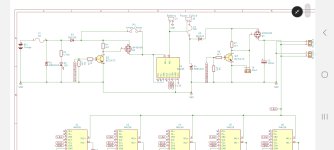
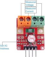
I have questions about the Inas or charging currents. Are they reduced by the firmware or hardware!?
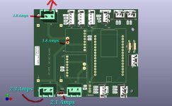
I bought a more powerful power supply to charge the batteries, but I noticed that it is limited; when I charge via the charging station I can get a maximum of 1.5 amps.
If I charge the battery directly, it charges with 6 amps, which would mean 1C for my battery because it supposedly has 6000 mah.
could that be changed or adapted?
Hallo,
ich habe Fragen zu den Inas bzw. Ladeströmen. werden die durch die Firmware bzw. durch die Hardware reduziert!?
Ich habe mir ein Stärkeres Netzteil zum Aufladen der Akkus zugelegt, dabei ist mir aufgefallen das es Limitiert ist, wenn ich über die Ladestation Lade, komme ich auf maximal 1.5 Ampere.
Lade ich den Akku direkt, dann läd er mit 6 Ampere was bei meinem Akku 1C bedeuten würde weil er angeblich 6000mah hatt. Könnte mann das Ändern bzw anpassen?
I have questions about the Inas or charging currents. Are they reduced by the firmware or hardware!?
I bought a more powerful power supply to charge the batteries, but I noticed that it is limited; when I charge via the charging station I can get a maximum of 1.5 amps.
If I charge the battery directly, it charges with 6 amps, which would mean 1C for my battery because it supposedly has 6000 mah.
could that be changed or adapted?
Hallo,
ich habe Fragen zu den Inas bzw. Ladeströmen. werden die durch die Firmware bzw. durch die Hardware reduziert!?
Ich habe mir ein Stärkeres Netzteil zum Aufladen der Akkus zugelegt, dabei ist mir aufgefallen das es Limitiert ist, wenn ich über die Ladestation Lade, komme ich auf maximal 1.5 Ampere.
Lade ich den Akku direkt, dann läd er mit 6 Ampere was bei meinem Akku 1C bedeuten würde weil er angeblich 6000mah hatt. Könnte mann das Ändern bzw anpassen?