You are using an out of date browser. It may not display this or other websites correctly.
You should upgrade or use an alternative browser.
You should upgrade or use an alternative browser.
45ZW2430 24V DC 28W Brushless Motor & 12-36v 500w Brushless Driver
- Thread starter Sascha
- Start date
Hi Sascha and Bernard. If I understand, we have a 3.3V PWM Signal coming out the Teensy, who needs to be converted in a 0-5V analogique signal.
If we just connect the PWM signal to the BL Driver, the frequency of this signal will maybe destroy the electronic components of the driver.
Maybe the use of such a card could help ?
For the direction and the others digital outputs, the use of a logic level converter module should be enough.
I think I will test with those components.
The question who's remaining.... how to simulate my 3.3V PWM signal... .
In other case, in this video, the guy is only using an analogique functions in the programm .
I've just opened the ardumower software... oh my Godness....
Last edited:
Exactly.Hi Sascha and Bernard. If I understand, we have a 3.3V PWM Signal coming out the Teensy
I hope no but only a test can give the answerIf we just connect the PWM signal to the BL Driver, the frequency of this signal will maybe destroy the electronic components of the driver.
 ,Maybe the driver can use the PWM instead analogue voltage.It's certainly what you see in the video
Yes ! ")
my family was asleep.. that's why I talked very low...
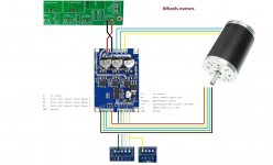
Both directions are ok and you can change of course the speed. Stop also tested as the motor was driving.
On the Arduino Uno there are only 6 PWM outputs that's why I had to change the pin number from 2, to 3 who's a pwm output and it works.
The 5V link from the driver to the Uno card must not be connected, because thisone is only used to bring 5V ON the Uno if you don't have an other source for your Uno. I've disconnected it later with less temperatur for the Driver; if your USB cable is connect you have already 5V on your Arduino Uno, and it will be the same with our TeensyPCB.
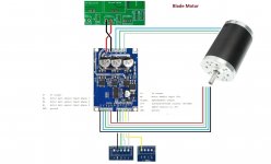
And this is how I should connect my motors after my tests.
my family was asleep.. that's why I talked very low...
Both directions are ok and you can change of course the speed. Stop also tested as the motor was driving.
On the Arduino Uno there are only 6 PWM outputs that's why I had to change the pin number from 2, to 3 who's a pwm output and it works.
The 5V link from the driver to the Uno card must not be connected, because thisone is only used to bring 5V ON the Uno if you don't have an other source for your Uno. I've disconnected it later with less temperatur for the Driver; if your USB cable is connect you have already 5V on your Arduino Uno, and it will be the same with our TeensyPCB.
And this is how I should connect my motors after my tests.
Attachments
Last edited:
Cool .. ")
What is the PWM frequency in your test ?
See:
 arduinoinfo.mywikis.net
and if you use D3 as PWM maybe add in the setup :
TCCR2B = TCCR2B & B11111000 | B00000010; // set timer 2 divisor to 8 for PWM frequency of 3921.16 Hz
To have a higher frequency.
Now you need to test ( only the PWM and DIR part because the odometry can work at 5V ) with a 3.3V module like ESP8266.
here a sample of code i use with weemos D1 esp8266.
What is the PWM frequency in your test ?
See:
Arduino-PWM-Frequency - ArduinoInfo
and if you use D3 as PWM maybe add in the setup :
TCCR2B = TCCR2B & B11111000 | B00000010; // set timer 2 divisor to 8 for PWM frequency of 3921.16 Hz
To have a higher frequency.
Now you need to test ( only the PWM and DIR part because the odometry can work at 5V ) with a 3.3V module like ESP8266.
here a sample of code i use with weemos D1 esp8266.
Code:
//Test motor using 2 pins
//send the PWM to PIN 6
//Send the DIR to PIN7


const int PwmPin = D6;
const int DirPin = D7;
int MinPwmValue = 0; // avoid to start at pwm=0 to have high torque on motor start
int MaxPwmValue = 200;

void setup() {
  Serial.begin(115200);
  pinMode(PwmPin, OUTPUT);
  analogWrite(PwmPin, 0);
  pinMode(DirPin, OUTPUT);
  digitalWrite(DirPin, HIGH);

  //this line for ***ARDUINO NANO***set the pwm frequency to pin 6 but affect  the millis() function
 // TCCR0B = TCCR0B & B11111000 | B00000010; // for PWM frequency of 7812.50 Hz
  //this line set pwm frequency to 10 Khz on ESP8266 tested with weemos D1
  analogWriteFreq(10000);
}

void loop() {
  //forward accelerate and brake
  Serial.println("Forward");
  digitalWrite(DirPin, HIGH);
  for (int Value = MinPwmValue; Value < MaxPwmValue; Value++) {
    analogWrite(PwmPin, Value);
    delay(20);
  }
  for (int Value = MaxPwmValue; Value >= MinPwmValue; Value--) {
    analogWrite(PwmPin, Value);
    delay(20);
  }
  // pause between
  delay(1500);
  Serial.println("Backward");
  //reverse accelerate and brake
  digitalWrite(DirPin, LOW);
  for (int Value = MinPwmValue; Value < MaxPwmValue; Value++) {
    analogWrite(PwmPin, Value);
    delay(20);
  }
  for (int Value = MaxPwmValue; Value >= MinPwmValue; Value--) {
    analogWrite(PwmPin, Value);
    delay(20);
  }
  // pause between
  delay(1500);

}This is the code used; I think the default frequency is used.
Code:
#include <ArduinoJson.h>
//#######################################
//#######################################
// GPIO mappings for Arduino Mega 2560
//#######################################
int m1_EL_Start_Stop=5;  //EL
int m1_Signal_hall=2;   // Signal - Hall sensor
int m1_ZF_Direction=4;  // ZF
int m1_VR_speed=3;    //VR
//#######################################
//#######################################
int pos=0;int steps=0;int speed1=0;
String direction1;
//#######################################
//#######################################
void plus() {
  pos++; //count steps
  Serial.println(pos);
    if(pos>=steps){
    wheelStop();
    pos=0;
  }
}

void setup() {

// put your setup code here, to run once:
Serial.begin(115200);

//wheel 1 - Setup pin mode
pinMode(m1_EL_Start_Stop, OUTPUT);//stop/start - EL
pinMode(m1_Signal_hall, INPUT);   //plus       - Signal
pinMode(m1_ZF_Direction, OUTPUT); //direction  - ZF

    //Hall sensor detection - Count steps
    attachInterrupt(digitalPinToInterrupt(m1_Signal_hall), plus, CHANGE);
}


void drive(){
// {"direction":"forward","steps":"30","speed":"50"}
// {"direction":"backword","steps":"30","speed":"50"}
// {"direction":"stop","steps":"0","speed":"0"}--

      if(direction1=="forward" && pos<steps){
        wheelMoveForward();
      }else if(direction1=="backword" && pos<steps){
        wheelMoveBackward();
      }else{
        Serial.println("Stop");
        wheelStop();
        pos=0;
      }
 }


void wheelStop(){
  digitalWrite(m1_EL_Start_Stop,LOW);
}

void wheelMoveForward(){
      analogWrite(m1_VR_speed, speed1);
      digitalWrite(m1_EL_Start_Stop,LOW);
      delay(1000);
      digitalWrite(m1_ZF_Direction,HIGH);
      delay(1000);
      digitalWrite(m1_EL_Start_Stop,HIGH);
}

void wheelMoveBackward(){
      analogWrite(m1_VR_speed, speed1);
      digitalWrite(m1_EL_Start_Stop,LOW);
      delay(1000);
      digitalWrite(m1_ZF_Direction,LOW);
      delay(1000);
      digitalWrite(m1_EL_Start_Stop,HIGH);
}

void loop() {

  if (Serial.available()>0) {
    String command=Serial.readString();

      DynamicJsonBuffer jsonBuffer;
      JsonObject& root= jsonBuffer.parseObject(command);

       if (root.success()) {
          direction1 = root["direction"].asString();
          Serial.println(direction1);
          steps = atoi(root["steps"]);
          Serial.println(steps);
          speed1 = atoi(root["speed"]);
          Serial.println(speed1);
          drive();
       }
}


}I used an industrial 24V power supply, but didn't mesured amps.. . For the cutter, I found this document who gives 2.4A and for traction motors, thisone who gives 0.9A.
But, I just tried one more time and with a wheel on traction motor to charge it, and I had less than 1A; on cutter motor I had 2 Amps on holding the axe of the motor with my thingers but I thought not much torque on starting... . So I think you're in the right ranges.
But, I just tried one more time and with a wheel on traction motor to charge it, and I had less than 1A; on cutter motor I had 2 Amps on holding the axe of the motor with my thingers but I thought not much torque on starting... . So I think you're in the right ranges.
Today i have tested the BL motor driver from Marotronics shop.
In my case the teensy can't manage the enable function of the driver , so I have shunt the 5V out of the driver to the EL input to have motor working and PWM and Odomotry are OK.
Did EL work for you with only 3.3V ,it's note 5V on schematics ???
In my case the teensy can't manage the enable function of the driver , so I have shunt the 5V out of the driver to the EL input to have motor working and PWM and Odomotry are OK.
Did EL work for you with only 3.3V ,it's note 5V on schematics ???
I have stop the test with the driver from the ardumower shop.
The issue was a random start with delay and the very slow acceleration of the driver.
I use instead this one and the result is perfect actually ,but need many hour test to be sure.
The only issue is the noise in the perimeter mag , so i need to check again the code.

I also discover a issue in the power PCB ,one track don't have the correct width.
It's better to use the MOW2 part and put the INA226 without shunt for i2c adress in this location.

The issue was a random start with delay and the very slow acceleration of the driver.
I use instead this one and the result is perfect actually ,but need many hour test to be sure.
The only issue is the noise in the perimeter mag , so i need to check again the code.
I also discover a issue in the power PCB ,one track don't have the correct width.
It's better to use the MOW2 part and put the INA226 without shunt for i2c adress in this location.