Ich habe in den letzten Monaten, mit Bernard aus dem Ardumower Forum, eine einfache und simple Platine für den Ardumower entworfen.
Die Platine hat keine SMD Bauteile und kann von jedem, der einen Lötkolben halten kann, in kürzester Zeit selber gelötet werden.
Für einen funktionierenden Mähroboter werden folgende Teile benötigt:
1x DUE_PCB_V1.01
1x Charging_PCB
Software: Azuitber
Motortreiber mind. 3 (L298N/BTS7960B)
Akku
Motoren
Die passenden Gerber Dateien sind in meinem Github Account zu finden.
Wer sie nicht selber bestellen will, kann mir eine PM schicken und sie bei mir erwerben.
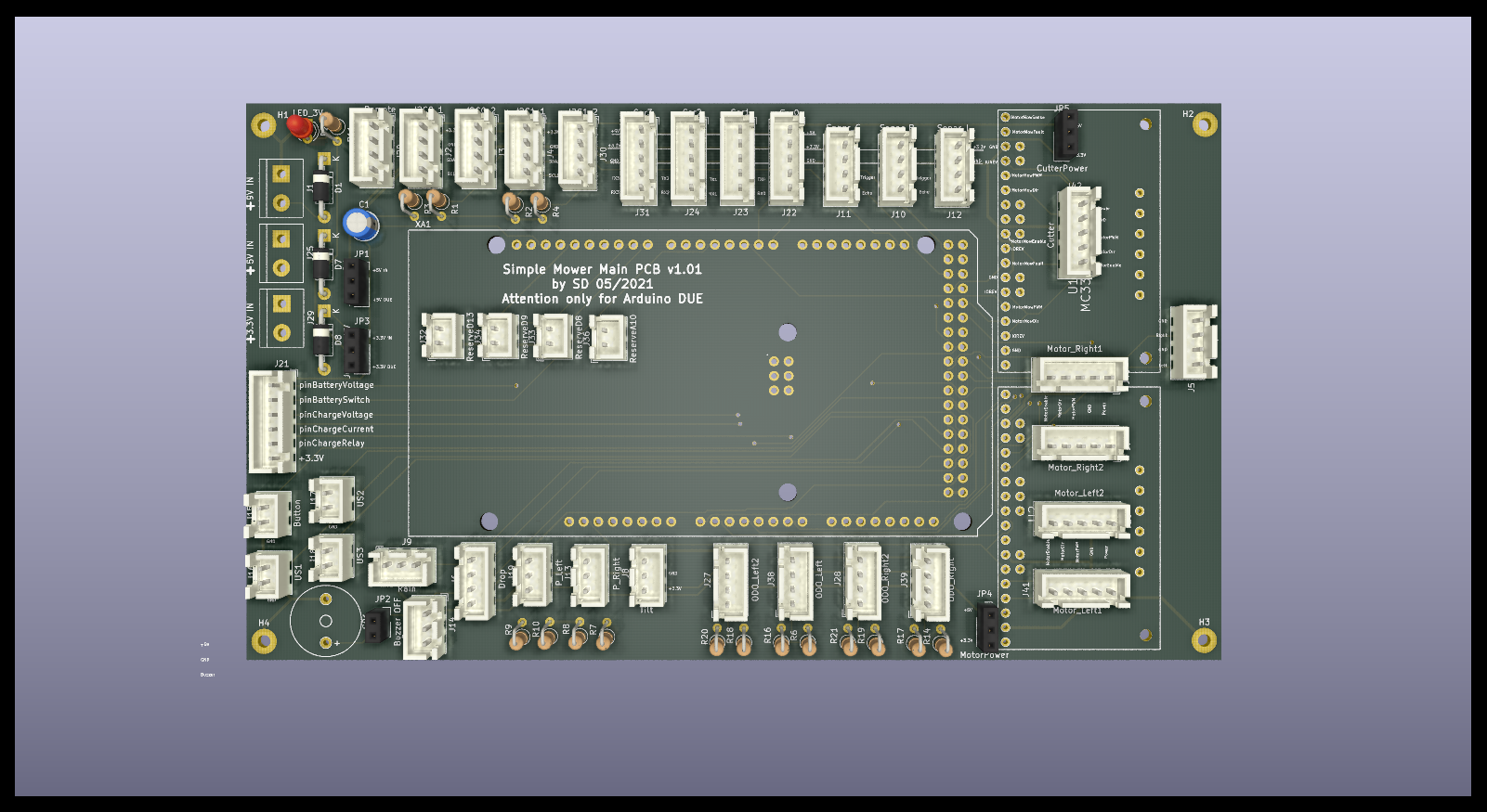
Die Hauptplatine:
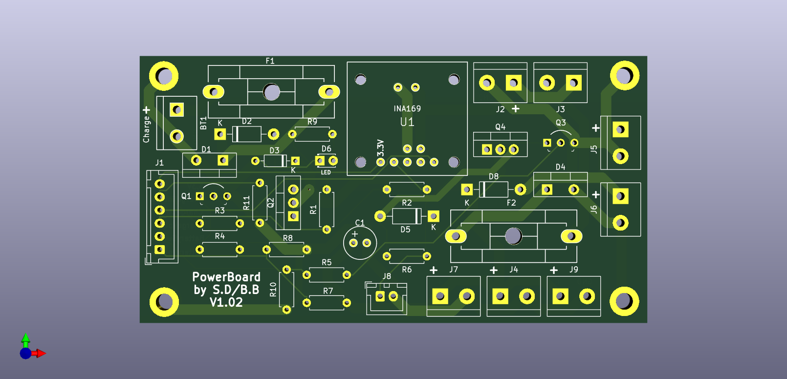
Power/Charging PCB:
Die Platine hat keine SMD Bauteile und kann von jedem, der einen Lötkolben halten kann, in kürzester Zeit selber gelötet werden.
Für einen funktionierenden Mähroboter werden folgende Teile benötigt:
1x DUE_PCB_V1.01
1x Charging_PCB
Software: Azuitber
Motortreiber mind. 3 (L298N/BTS7960B)
Akku
Motoren
Die passenden Gerber Dateien sind in meinem Github Account zu finden.
Wer sie nicht selber bestellen will, kann mir eine PM schicken und sie bei mir erwerben.
Die Hauptplatine:
Power/Charging PCB:
Last edited:
") )
)
