Robomow RL850 rebuild

Bruno

Member
Hello,
my two RL850 are dead, with hardware problems related to the motherboard. It's time to replace them!
My idea is to use Ardumower software but i have a lot of doubts on the hardware. On this site there are two PCB: one for the teensy and one for Arduino Due. Which one is more stable and ready to be used?
What do i need to rebuild a RL850 other than the main pcb? A perimeter wire receiver/sender? A motor driver?

Thanks,
Bruno
 
The RL850 has brush motors, if I know that correctly?
Then you would need the TeensyMainPCB v1.3 (not quite ready yet) and the PowerPCB 1.2. But only if you want to lay a perimeter wire. The TeensyPCB does not work with the Ardumower RTK GPS. You also need the perimeter transmitter, either from the Ardumower or from Bernard.

Bernard will certainly write something here, he has the larger version of the Robomower.
 
No problem to rebuild a RL 850 with teensy PCB actual version or next one.
I use a RL2000 with teensy PCB without issue.
You need to be sure that all the mechanics is GOOD (motor gear)
You need to have access to 3D printer to build the odometry
You need 5 BTS7960 DC motors driver
And a new LI-ION 10Ah battery with BMS.
Thanks for the reply.
I've read the wiki and all the docs i've found and i still have a couple of doubts.
1 - Checked the mechanics and yes, it's good
2 - Yes i have. But i also need two Azdelivery ky-003, and 64 magnet 3x2, right?
3 - 5x BTS7960. I guess 3 for the mowing motors and 2 for wheels? No MC33926 (that is quite expensive...)?
4 - Battery: yes ready. But i don't have the original RoboMow charging station. I can start without it but in the future it can be useful. Can i 3d print it? Can i modify RL850 to dock and charge into a charging station?
5 - Is GY-87 mandatory? Which one i must use? GY-87 or GY-88
6 - Perimeter Wire. I've found the instructions to build the sender but not for receiver.
7 - I'm targeting the minimum BOM, just to start. I've also bought: INA226 with R010, BT HC 05. What else?

Thanks!!!
Bruno
 
2-Yes
3-Yes MC33926 is for ardumower PCB but you need teensy PCB.
4-Battery Here it's more complex ,If you use LI-ION one the charging process is managed by the charger , but with lead acid you need a special charger.
5 You need a GY-521 IMU directly connected on PCB.
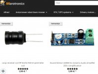
6 It's the receiver from Marotronics, it's better to use 2 of them . https://wiki.ardumower.de/index.php?title=Perimeter_sender_(English)#Receiver
Capture d’écran 2022-06-21 222359.jpg
You need
1 Teensy 4.1
2 ESP32 DEV KIT V1 (one for mower and one for sender) V1 is important to have the correct pinout.
5 INA226 with R010
1 Power PCB last version
1 Main PCB
1 Sender PCB or you need to use many wire.
1 DC/DC voltage to create the 5V for main pcb from 24V


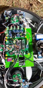
Here the result:
20211018_134515.jpg

And video:
 
Thank you!
I've bought almost all the parts, and i hope to receive everything soon.
Just another question for PCB:
i've not found PowerBoard 1.07 gerber files. Is it correct?

Bruno
 
Just a quick update: i received PCBs and the first batch of components. Time to solder and do some tests.
Where i can find STL to mount pcb on the RL850 ? On the Boilevin github page there are files for the odometry but not for the T-Mow board.

Thanks
 
Thank you!

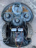
First step: i've cleaned it and removed the two rusty heavy iron cylinder on the front.

The 4 sensors used to detect the perimeter cable, the one on the caster wheel and all temp sensors are now useless, right?

On the pcb i can connect two perimeter sensors, what is the best place to put them? No sensors on the back of the RL850?


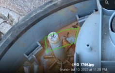
IMG_1766.jpg
 
The 4 sensors used to detect the perimeter cable
You can reuse the small coil (so keep this part)
The iron cylinder on the front are needed only if you keep the lead acid battery.
what is the best place to put them?
receiver location.jpg


Here on each front side .


gear box remove.jpg

To remove the gear box you need to push on each side of the plastic chassis to remove the metal gear axe.
 
View attachment 578

To remove the gear box you need to push on each side of the plastic chassis to remove the metal gear axe.

Hi,
i'm slowly working on this job, now it's time to mount the magnetic odometer. I haven't understood what is the sequence to install the new 'magnetic' wheel. Do i need to disassembly the entire gearbox?

Thanks!
 
Hi,
i'm slowly working on this job, now it's time to mount the magnetic odometer. I haven't understood what is the sequence to install the new 'magnetic' wheel. Do i need to disassembly the entire gearbox?

Thanks!
Yes.
 
After some months i'm back on the project of rebuilding a RL850.
I've mounted the two boards and uploaded the firmware. I'm stucked with the PowerBoard not found in the Teensy log.
My Power pcb is 1.06. Are there any issues with this pcb? I'm not able to find any errors so i will start building another one (that i already have). What are the minimum sets of components needed to talk with the main board?

Thanks,
Bruno
 
I'm stucked with the PowerBoard not found in the Teensy log.
Check SDA and SCL order in the ina226 ship to see if it's ok according to the PCB.
Check the shunt at back of the INA226.
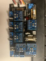
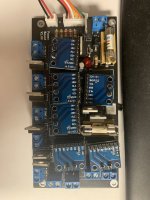
Send image of the assembled Power PCB
 
Check SDA and SCL order in the ina226 ship to see if it's ok according to the PCB.
Check the shunt at back of the INA226.
Send image of the assembled Power PCB
Here it is, thanks for your help!
 

Attachments

  • IMG_3232.jpg
    IMG_3232.jpg
    827.5 KB · Views: 12
  • IMG_3233.jpg
    IMG_3233.jpg
    797.7 KB · Views: 11
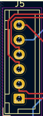
On some INA226 board the SCL SDA pin are swap
Your SCL and SDA are inverted comparing to PCB.
Simply swap SCL0 SDA0 and SCL1 SDA1 on J5 connector, but i see black and red wire on strange location on J5 3.3V is normaly at top of connector.
Capture d'écran 2023-06-16 132713.png
 
Back
Top