You are using an out of date browser. It may not display this or other websites correctly.
You should upgrade or use an alternative browser.
You should upgrade or use an alternative browser.
Oled Screen ?
- Thread starter LaurentS
- Start date
It's easy on Teensy (do not need change in code ,only Into arduremote setting Rain Temp Humid menu enable screen use (ONLY IF SCREEN IS CONNECTED or navigation is really slow)
Sorry I need to rename the menu
You can see all the AZURITBER info :
 wiki.ardumower.de
Sorry I need to rename the menu
You can see all the AZURITBER info :
AzuritBer Firmware (English) – www.wiki.ardumower.de
Hello,
I try to connect a 1.3" oled screen to the teensy, but the teensy won't accept it. (Main PCB is the V1.03)
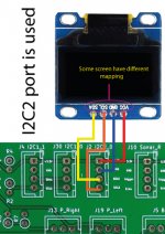
Connector on I2C2_1


in the screen.cpp I have the settings:
I tested the screen with the I2C scanner sketch and these will detected and the detected address is 0x3C (on a bread board with an ESP32 tested)
If I select in the pfod app SCREEN > YES, than after some seconds change back to NO and in the teensy serial console comes the next message:
Any idea what can I try to get the oled screen to work?
EDIT: small update. The I2C scanner on the teensy recognize all the i2c devices;
I think I will have to try some other configurations of the display driver. Maybe is it a "U8X8_SSD1306".
I try to connect a 1.3" oled screen to the teensy, but the teensy won't accept it. (Main PCB is the V1.03)
Connector on I2C2_1
in the screen.cpp I have the settings:
// Please UNCOMMENT one of the contructor lines below
// U8x8 Contructor List
// The complete list is available here: https://github.com/olikraus/u8g2/wiki/u8x8setupcpp
// Please update the pin numbers according to your setup. Use U8X8_PIN_NONE if the reset pin is not connected
//U8X8_SSD1306_128X64_NONAME_HW_I2C u8x8(/* reset=*/ U8X8_PIN_NONE);
//U8X8_SSD1306_128X64_ALT0_HW_I2C u8x8(/* reset=*/ U8X8_PIN_NONE); // same as the NONAME variant, but may solve the "every 2nd line skipped" problem
U8X8_SH1106_128X64_NONAME_HW_I2C u8x8(/* reset=*/ U8X8_PIN_NONE);
U8G2_SH1106_128X64_NONAME_F_HW_I2C u8g2(U8G2_R0, /* reset=*/ U8X8_PIN_NONE);
I tested the screen with the I2C scanner sketch and these will detected and the detected address is 0x3C (on a bread board with an ESP32 tested)
If I select in the pfod app SCREEN > YES, than after some seconds change back to NO and in the teensy serial console comes the next message:
Warning screen management duration > 100 ms : 4080.00
Screen is disabled
Any idea what can I try to get the oled screen to work?
EDIT: small update. The I2C scanner on the teensy recognize all the i2c devices;
Scanning(Wire)...
Device found at address 0x40 (PCA9685,Si7021)
Device found at address 0x41 (STMPE610,PCA9685)
Device found at address 0x44 (PCA9685, SHT3X)
Device found at address 0x68 (DS1307,DS3231,MPU6050,MPU9050,MPU9250,ITG3200,ITG3701,LSM9DS0,L3G4200D)
done
Scanning(Wire1)...
Device found at address 0x40 (PCA9685,Si7021)
done
Scanning(Wire2)...
Device found at address 0x3C (SSD1306,DigisparkOLED)
done
I think I will have to try some other configurations of the display driver. Maybe is it a "U8X8_SSD1306".
Last edited:
Fürst Ruprecht
Well-known member
Meine Displays sind noch auf dem Weg.
Ich wollte an Arnold (dem "Starken") die Kennschilder vorn und hinten mit Displays umsetzen, damit ich in der Radarkontrolle das Kennzeichen ändern kann!
Nebenbei will ich aber auch Werte im Betrieb am Mäher anzeigen, weil ich zur Zeit keine Web-Server Lösung installiert habe. Für die Fehlersuche ist MissionPlanner nicht wirklich so praktisch.
Okay. Heute habe ich einen Test-Sketch in der Arduino IDE gemacht. Auf ein ESP32 habe ich mit folgendem Code den Display zum Leben erweckt:
Okay. Today I made a test sketch in the Arduino IDE. I brought the display to life on an ESP32 with the following code:
The build up is very puritan, but there is a positive result:

Der einzige Unterschied zum Code in Teensymower, dass hier die SCL and SDA Pins der ESP32 in der Constructor definiert sind. Wenn ich diese Pin Definition weglasse, funktioniert die Oled nicht.
Also ich habe in der teensymower Code (screen.cpp) für die I2C_2 Port die Pins 24 und 25 versucht zu definieren.
Es wird compiliert aber gleiches Ergebnis. Es lässt die Oled leider auch so nicht aktivieren.
Hm. Entweder stimmt etwas mit meiner Library nicht, oder mit der I2C_2 Pin-Definition.
The only difference to the code in Teensymower is that the SCL and SDA pins of the ESP32 are defined in the constructor. Without this pin definition, the OLED doesn't work.
So I tried to define pins 24 and 25 in the teensymower code (screen.cpp) for the I2C_2 port.
It compiles without error, but the result is the same. Unfortunately, it doesn't activate the OLED.
Hm. Either there's something wrong with my library or with the I2C_2 pin definition.
Giving up is not an option... the show (mower) must go on!
Okay. Today I made a test sketch in the Arduino IDE. I brought the display to life on an ESP32 with the following code:
Der Aufbau ist sehr puritan, aber ein positives Ergebnis ist da:#include <U8g2lib.h>
#include <Wire.h>
#define SDA_0 22
#define SCL_0 21
U8G2_SH1106_128X64_NONAME_F_HW_I2C u8g2(U8G2_R0, /* reset=*/ U8X8_PIN_NONE, /* clock=*/ SCL_0, /* data=*/ SDA_0);
void setup()
{
u8g2.begin();
}
void loop() {
u8g2.clearBuffer(); // clear the internal memory
u8g2.setFont(u8g2_font_ncenB08_tr); // choose a suitable font
u8g2.drawStr(0,10,"Hello World!"); // write something to the internal memory
u8g2.sendBuffer(); // transfer internal memory to the display
delay(1000);
}
The build up is very puritan, but there is a positive result:
Der einzige Unterschied zum Code in Teensymower, dass hier die SCL and SDA Pins der ESP32 in der Constructor definiert sind. Wenn ich diese Pin Definition weglasse, funktioniert die Oled nicht.
Also ich habe in der teensymower Code (screen.cpp) für die I2C_2 Port die Pins 24 und 25 versucht zu definieren.
Es wird compiliert aber gleiches Ergebnis. Es lässt die Oled leider auch so nicht aktivieren.
Hm. Entweder stimmt etwas mit meiner Library nicht, oder mit der I2C_2 Pin-Definition.
The only difference to the code in Teensymower is that the SCL and SDA pins of the ESP32 are defined in the constructor. Without this pin definition, the OLED doesn't work.
So I tried to define pins 24 and 25 in the teensymower code (screen.cpp) for the I2C_2 port.
It compiles without error, but the result is the same. Unfortunately, it doesn't activate the OLED.
Hm. Either there's something wrong with my library or with the I2C_2 pin definition.
Giving up is not an option... the show (mower) must go on!
And Yeesss! The screen works finally! 

The problem was my U8g2 library! Unfortunatelly I have installed the u8g2 library in the IDE from the internet and so the compiler don't use the "U8x8lib.cpp" file in the teensymower directory! This file is adopted specially for the teensy board! It is important to define the I2C_2 port for the u8x8 routines. (in "U8x8lib.cpp" from line 1356 to 1381) Wire2. must defined for our teensy board. (standard in the u8g2 lib is "Wire.")
Otherwise the software looks for the screen on I2C_0.
In the "screen.cpp" you don't need any changes!
So, if you have a similarly problem with the OLED screen, make soure you do not have installed in your IDE any u8g2 library!")
The problem was my U8g2 library! Unfortunatelly I have installed the u8g2 library in the IDE from the internet and so the compiler don't use the "U8x8lib.cpp" file in the teensymower directory! This file is adopted specially for the teensy board! It is important to define the I2C_2 port for the u8x8 routines. (in "U8x8lib.cpp" from line 1356 to 1381) Wire2. must defined for our teensy board. (standard in the u8g2 lib is "Wire.")
Otherwise the software looks for the screen on I2C_0.
In the "screen.cpp" you don't need any changes!
So, if you have a similarly problem with the OLED screen, make soure you do not have installed in your IDE any u8g2 library!