You are using an out of date browser. It may not display this or other websites correctly.
You should upgrade or use an alternative browser.
You should upgrade or use an alternative browser.
MI632
- Thread starter Bernard
- Start date
ullisun58
Well-known member
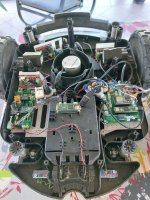
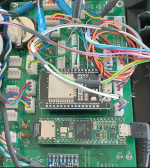
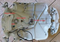
Her Bernard Great JobHere some picture and file to rebuild MI632 using Teensy PCB.
Main body with all parts
Main PCB V1.01 Wiring
What GPS Modul you are using? and what is the Pi Zero is doing?
It's M8N module, but was only for test ,It's not use actually. (Accuraccy +- 5 meters)Her Bernard Great Job
What GPS Modul you are using? and what is the Pi Zero is doing?
PiZero is used with PiArdu software for easy management over WIFI. (Debug, Teensy OTA Flash etc...)
Bernard, that is some awesome piece of work! Thanks for sharing the detailled pictures and all the effort you have put into this!
As the original mainboard has a water damage and a replacement costs >500€, I will definitely fix / upgrade my MI632 based on your design!
Never the less, there are some questions I have (right now - there's most likely more to come ;-) ):
1. Would it be possible to recieve the STLs of the 3D-Printed parts you used? This would make life easier, as I will not have to design them myself...
2. Would it be possible to recieve the configs you used for setting up the robot? (Or simply images of the Teensy and Raspi SD-Cards and the sketch for the ESP32?)
3. Are you using the original battery and charger? (If not: what are you using?)
4. Are you using some kind of odometry? Or is it "included" in the brushless motors?
5.1 At what distance from the center line have you installed the perimeter sensors?
5.2 Have you just left the perimeter wire at the original distance of about 30cm from the edges of the lawn?
6. What Resistor values are you using for R1, R2, R7 and R8? (2k and 1k as in the bom?)
7. (Maybe a "noob"-question) What is the "ARU"?
Again: Thanks for sharing this - this is really helpfull! I will also share my progress on the conversion.
1 Take a look at github: https://github.com/Boilevin/Teensy/tree/main/3D file/MI632Bernard, that is some awesome piece of work! Thanks for sharing the detailled pictures and all the effort you have put into this!
As the original mainboard has a water damage and a replacement costs >500€, I will definitely fix / upgrade my MI632 based on your design!
Never the less, there are some questions I have (right now - there's most likely more to come ;-) ):
1. Would it be possible to recieve the STLs of the 3D-Printed parts you used? This would make life easier, as I will not have to design them myself...
2. Would it be possible to recieve the configs you used for setting up the robot? (Or simply images of the Teensy and Raspi SD-Cards and the sketch for the ESP32?)
3. Are you using the original battery and charger? (If not: what are you using?)
4. Are you using some kind of odometry? Or is it "included" in the brushless motors?
5.1 At what distance from the center line have you installed the perimeter sensors?
5.2 Have you just left the perimeter wire at the original distance of about 30cm from the edges of the lawn?
6. What Resistor values are you using for R1, R2, R7 and R8? (2k and 1k as in the bom?)
7. (Maybe a "noob"-question) What is the "ARU"?
Again: Thanks for sharing this - this is really helpfull! I will also share my progress on the conversion.
2 For setup ,you simply need to select the correct platform and PCB into mower.h, but it's better to fully upload code into teensy before connecting to PCB and before cutting the power trace.
Code:
//**************************************************************
// ------- select one platform type -------------------
//**************************************************************
#define MI632
//#define YARDFORCE
//#define RL2000
//#define MOW800

//**************************************************************
// ------- select one mainPCB -------------------
//**************************************************************
//#define PCB_V101
#define PCB_V1034 Odometry is on the Driver
5.1 Perimeter sensor are centered in the front mower, you can see the 2 receivers on the first picture.
2*https://www.marotronics.de/Sound-Sensor-LM386-for-Arduino-Audio-Amplifier-200-x-amplification
and 2*https://www.marotronics.de/Loop-receiver-coil-11P-ferrite-150mH-perimeter-coil#tab-votes
5.2 the wire was not for MI632 and o don't move it .Mower mow near perimeter by following the right coil receiver.
6 For resistor, you need 8 of them 4 in 2K and 4 in 1K to reduce 5V voltage to 3.3V form odometry and wire receiver.
7 ARU is the emergency switch to isolate the battery from all electronics.
Thanks for the good explanations! That really helps. The first parts have already arrived and I will start printing the other parts tonight.
Ad 1: I saw your repo, but did not see the MI632 files in it... Thanks for sharing!
Ad 2: Thanks! I did not realize, the MI632 was already pre-configured in the code. That makes life much easier!
Ad 3: It's a 29V battery - pretty odd. So I will rather switch to 24V. I still have a battery from a Hoverboard sitting around. That will do the trick.
Ad 4: Perfect!
Ad 5: I saw them on the picture but was not sure wether the bot will try to hit the centerline inbetween them or rather focus on one of them - with that explanation it's clear. I will thus "calibrate" on the right hand sensor.
Ad6: Thanks!
Ad7: OK, I will wire it up accordingly.
Again: Thanks for all your explanations! As soon as I have all the parts I'll post my progress.
No it's OK 29,4V is the max voltage of a 24V battery.Ad 3: It's a 29V battery - pretty odd. So I will rather switch to 24V. I still have a battery from a Hoverboard sitting around. That will do the trick.
I only add the 3D file yesterday.
Simply take care to the DC/DC 24V to 5V locate between the POWER PCB and MAINPCB (adjust it to 5 V before connecting the main PCB).goes up in smoke
On power PCB always put a heat sink on the Battery to mower mosfet It's mandatory to manage the MOW and DRIVE motor.
NEVER connect the brake pin of the mow motor.
And normally NO SMOKE
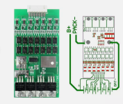
For battery it's possible that it's difficult to use the original one with it's own BMS,
But if you have some electronic knowledge : I use this kind of BMS without any issue:
