Robot Lawn Mower All Wheels Drive and Steer - Prototyp3, Neu Prototyp4

Mal eine Frage zu deinem ersten Tests bzw. dem blauen Mower aus einem früheren Video. Wie genau ist die Lenkung realisiert? Ich plane für den Winter einen weiteren Roboter, der aber eher wie ein Traktor zu sehen ist und der kein Mower sein soll. So ähnlich wie die ersten Lieferroboter oder Fendt Xaver. Allerdings mit Ackermann Lenkung und kein Skid-Steer.
Also wie genau bewegst du das Lenkgestänge? Aktuell plane ist mit einer zentralen Spindel und fixierten, angetriebenen Mutter.
 
Hallo Paddy,
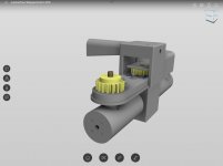
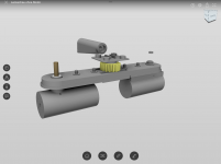
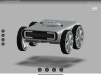
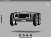
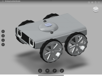
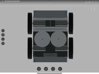
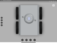
die „Vorderachse“ hat 7 Zahnräder. In den äußeren Zahnrädern ist ein 10mm senkrechtes Rohr befestigt, welches in einen Zylinder mündet, in welchem die Motoren befestigt sind. Es schwenken also bei Lenkeinschlag die Motoren mit. Das mittlere Zahnrad war einst angetrieben von verschiedenen Servos und von einem Stepper-Getriebemotor. Das ist eine lange Leidensgeschichte. Die restlichen Zahnräder überbrücken nur die Distanz/Spurbreite. Außerdem sitzt auf dem mittleren Zahnrad ein spezielles Poti (für, ich glaube, 1 Mio. Bewegungen). Das Poti gibt die Info über den aktuellen Lenkwinkel. Das mit den Servos und Steppermotoren können wir abkürzen, die Servos sterben den Hitzetod, der Stepper ist zu schwach oder zu langsam. Das ganze wird von einer Quertraverse gehalten.
Aktuell - und diese Lösung hält - sind die Räder nur noch durch die sieben Zahnräder mechanisch gekoppelt. Diese Kopplung erlaubt 180 Grad Lenkeinschlag, was bei einem Traktor nicht erforderlich ist. Also könnte man die Räder auch über eine Spurstange oder einen Riemen, ein Gurtband oder ähnlich koppeln.
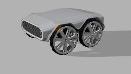
Die Lenkbewegung entsteht durch die individuelle Ansteuerung der Räder (in meinem Fall: DC-Getriebemotor, Brushed). Der Mäher hat 4 Motoren. Denkbar wäre auch ein Frontantrieb. Das Programm bestimmt die Bahnkurve und berechnet den Lenkwinkel, der resultiert. Weicht der Ist-Lenkwinkel vom Soll ab, wird auf die Vorderräder ein zusätzliches Moment gegeben (mehr PWM, oder mehr RPM, wie man will), linkes Rad und rechtes Rad im Vorzeichen invertiert. Dadurch drehen sich die Räder = lenken.
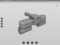
Für die aktuelle Konstruktion gibt es Fusion 360 Konstruktionsunterlagen. Die benötigten Teile kommen aus dem Baumarkt oder 3D-Drucker.
Der erste Prototyp hatte eine Spurstange. Das war beim Mäher von Nachteil, weil der Standard-Code aufgrund der größeren Wendewinkel stark überarbeitet werden mußte. Grundsätzlich funktioniert das aber, man braucht halt mehr Betriebszustände.
Ein ganz zentraler Punkt ist das Fahrzeuggewicht. Wenn das Gewicht hoch ist, versagen die üblichen Antriebe (weil zu schwer, zu schwach, zu langsam, zu klein, zu viele Störsignale). Ich hatte einen Futaba-Servo, den größten, den sie haben ( 20Kg/cm / 250€ ), der lief toll, super schnell, präzise, brauchte eine extra gepufferte, separate Stromversorgung und war nach einem Tag kaputt ( das 2x ).
Daher ist meine Empfehlung keinen separaten Antrieb zu verwenden.

Wenn Du mehr Details brauchst - kein Problem.

Gruß Fürst Ruprecht

die Bilder sind evtl. nicht letzter Stand, nur zum Eindruck gewinnen
 

Attachments

  • E7ED5AA7-6264-4DD3-BE5A-5F80A08BB2BA.png
    E7ED5AA7-6264-4DD3-BE5A-5F80A08BB2BA.png
    592.6 KB · Views: 17
  • FE94279E-6D5C-4231-818F-E4ADA0DB2364.png
    FE94279E-6D5C-4231-818F-E4ADA0DB2364.png
    514.5 KB · Views: 15
  • 10108EBF-4454-458F-A97A-DF4A6C5A47B9.png
    10108EBF-4454-458F-A97A-DF4A6C5A47B9.png
    461.5 KB · Views: 17
Danke für die ausführliche Antwort. Über die Art der Lenkung, ohne Lenkmotor, habe ich mich jetzt gewundert. Musste das zweimal lesen um zu verstehen.
Aber wenn es so klappt, schöne Lösung.

Bei mir kommen wieder Radnabenmotoren zum Einsatz. Alternativ auf eine Achse einfache Räder.

Servo und Stepper hatte ich schon mit Fragezeichen versehen und du bestätigt, dass es nichts wird. Aktuelle Idee ist eine Spindel und angetriebene Mutter als Lenkgetriebe zu verwenden. Im Prinzip wie an (m)einer CNC. Mutter dreht, wird aber in Position gehalten. Dadurch bewegt/verschiebt sich die Spindel, welche die Schenkel mit den Rädern dreht. Angetriebenen wird die Mutter per Riemen von einem DC Getriebemotor. Positionserfassung wie bei Dir.

Ich berichte dann in einem separaten Thread, sobald es was zu berichten gibt.
 
Interim report Prototype3:
The fixed wheels lead to high torques when driving in a circle and put a load on the chassis. The lawn suffers from the rubbing wheels. The high torques when cornering lead to step losses in the motor. The motor tries to catch up on the lost steps. This leads to a beating in the entire drive train, comparable to an impact wrench. So far, all wheels have been loose after a short time, clamp connection is impossible (not even with a lot of superglue). I have now drilled through the shafts and attached the wheels positively/fromschlüssig (but the attachment will deflect). I have read that the torque drops significantly (30%) when the motor is controlled with partial steps/microsteps. Therefore I will try it again with full step control. If the motor loses step sequence, the wheel will spin in a random direction. As a result, the CPU loses control on the mountain and the mower drives downhill. In my application/design - no speed control (because not really necessary with the stepper), mountain driving, cutting height at approx. 8-10 cm - this concept is overtaxed from the current point of view. However, it must also be said that in autumn when the grass is wet and the ground is damp, the Prototyp2 all-wheel mower is also subjected to significantly greater demands.
 
Prototype2 (Azurit with FR-Mod for 4WD): I have added the double reduction of the driving speed in the perimeter area in STATE-FORWARD. When approaching the wire, the mower will slow down. The reverse speed remains unchanged. Since the lawn is usually damp/wet in autumn, as is the ground, the wheels tend to spin at the high cutting height of 8-10 cm (the braking torque of the lawn on the chassis and the mowing guard also play a decisive role here). Unfortunately, the odometry of the standard mower is not suitable for cornering. I'm currently trying to adapt to single wheel steering so that the torque of all wheels is increased when the car is stationary. Actually, you would have to record the actual speed of all wheels. Unfortunately, the speed detection for the front wheels is missing (->Prototype4).
The omission of the motor for the steering of the front wheels also shows that the wear and tear due to the lack of steering torque has drastically decreased - the parts hold up (without problems). I have changed the potentiometer for angle detection (should be able to turn 1 million revolutions) once - this will probably continue to be necessary. What is unpleasant is that due to the omission of the steering motor (arranged in the middle of the front axle), the play of the gears now has a greater effect and the front wheels no longer run so parallel. An update is needed for 2023.

If I compare the two concepts from today's perspective, I would give preference to the 4-wheel drive with a self-steering front axle. I expected the very short Bobcat concept to be significantly better in terms of off-road capability and turning ability, which is not the case. On the contrary, the short wheelbase causes the mower to roll over on slopes. Rubbing the wheels when cornering also weighs a lot heavier than expected.
 
Prototyp3B -> breiter, einfacher, BLDC-Antriebs-Motoren mit integriertem Treiber

Small interim report: The BLDC geared motors with integrated driver have arrived. I ran them with a simple program on an esp32. If you connect the signal lines directly to the esp32 pins at 3.3V, everything works fine, but the motor only reaches half speed. With a level adjustment to 5V (with a simple collector circuit and NPN transistor) the motor reaches the full number of revolutions. It is interesting that the signal lines only have to be connected to ground - the 5V level is set automatically on the driver side. This makes level adjustment very easy, you only need a base resistor and an npn transistor. For the small four-wheel mower, I will remake the base plate because of the different BLDC-motor geometry and also adjust the cutting width to 2x15cm. The circuit board has already been rebuilt. I also revised the housing for the 3D printer, it is now much simpler in design. The torque of the motors seems to be significantly higher, but that still needs to be checked.

Prototyp4 -> Monster Mower !

For the Prototype-4 (2023 Edition) I have two hoverboards as part donors. The BLDC drivers have already arrived. The electronics should have two levels. For the basic electronics, I will adopt the existing concept of the prototype 3 (Teensy), but due to the lack of parts I will try to measure the current with operational amplifiers and AD converters.
A beagleboneblue board is to be used for the higher-level electronics. It runs Linux and the ardupilot software. Missions can be planned with the "MissionController" (PC or Pad). There are ready-made tools for recording the mowing area and calculating the lanes. It can also be switched between RTK operation and perimeter within the mission. The beaglebone board is controlled manually with rc-remote. In the automatic/mission mode, it sends the driving signal to the Teensy instead of the current RC remote control. At the moment it is unclear for me how I will switch between RTK and perimeter operation. I'm waiting for the new rc-remote, unfortunately my current one is not compatible with the beaglebone board. I already have the beaglebone board and the software is running. I tried to emulate the rc-remote with an esp32, but that only works to a limited extent.

Gruß Fürst Ruprecht

photo: Prototype-3B (in Fusion360)
 

Attachments

  • Prototyp3breiter.jpg
    Prototyp3breiter.jpg
    88.6 KB · Views: 11
Last edited:
Unfortunately I can't get the RC control on the BeagleboneBlue to work. I've been working on it for 3 weeks now with no success. So I got myself a Pixhawk 2.4.8 (clone). This works with the RC control without any problems. In the next few days I will rebuild the Prototyp_3 and make it ready to drive. Then the Pixhawk should control via Servo-Out -> the Teensy via RC-Control-In.
 
Prototype_3 is driving again.
The new chassis is built and the new BLDC motors are mounted and running. Unfortunately, the Teensy (the current No. 3) has taken a damage - solder bridge on the circuit board has led to a loss of one output.
I connected the pixhawk to the teensy board as described. Now the pixhawk controls the Teensy in RC mode. So far everything works as planned.
 
Update:
Two simpleRTK2B boards (Base+Rover ~ 630€) are running in my room. Without a clear view of the sky and without a metal base plate, the signal fluctuation is already less than 25cm. The radio connection between base and rover runs via xbee.
The connection between Rover (Pixhawk ~120€) and PC (Ground Station) runs via 3DR radio (433MHz, ~100€). With an esp32 I can request and receive data from the pixhawk via TX2/RX2. I can currently also send distance values from 4 ultrasonic sensors back to the pixhawk from an esp32. It is now possible to transfer the sensor values installed in the mower to the Pixhawk and in return to use the control signals from the Pixhawk for the mower. From a cost perspective, that doesn't make much sense at the moment. The hardware would have to be simplified here.
I built the pixhawk and the simpleRTK2B board into a housing that can be attached to the mower with Velcro fasteners (Klett-Verschluß). I would like to be able to use the "RTK" function as a flexible addon in different mowers.
 
A lot of money to play with, unfortunately I don't have it at the moment, I still have to set up my 2 metre aquarium and buy lighting, it's expensive enough.
But I find your ideas really interesting, keep us up to date.
 
Design inspired by Princess Ruprecht
 

Attachments

  • 0C52C788-8783-4900-A0F8-936F53875C5A.png
    0C52C788-8783-4900-A0F8-936F53875C5A.png
    1.9 MB · Views: 7
  • 179FABDA-D08C-4966-9E57-01C51A122B48.png
    179FABDA-D08C-4966-9E57-01C51A122B48.png
    1.4 MB · Views: 7
  • F746A9C8-4C54-49C5-88DA-73459B42DC4F.png
    F746A9C8-4C54-49C5-88DA-73459B42DC4F.png
    2.5 MB · Views: 6
  • C38DE42B-01E4-4075-9C29-C657B6FAF3B3.png
    C38DE42B-01E4-4075-9C29-C657B6FAF3B3.png
    1.1 MB · Views: 7
  • 68A74BC3-F0DF-4022-860A-ED6E9123DE01.png
    68A74BC3-F0DF-4022-860A-ED6E9123DE01.png
    1.9 MB · Views: 11
Base plate with motors:
- Drive: BLDC with integrated driver
- Mowing: DC motor with clocked transistor
- Grid for filter mat of cooker hood
- 1 fan for mower electronics / motors
- 1 fan for Teensy / Board
- Height-adjustable mower (manually)
- Perimeter receiver ( double: left / right )

BC822DC2-8054-4575-92E5-CB1205A34063.jpegB6FE162C-314E-4146-931E-4F017C7B6F8A.jpeg8B64FBFC-8353-4CC7-B1BA-6E34AC6A2E9E.jpeg92E46EA7-6DFA-40AF-9DB5-380043226B57.jpeg1CBB6DA1-DA1F-4E08-B0F1-EC4110A95066.jpeg91A6EFF3-9711-43D6-8FEF-2FBB8D94B8AB.jpeg
 
9F2AB8C0-D31C-486A-9A12-2552B77A4694.jpegE24F041D-953B-4CCB-85CA-D5E84FB07845.jpeg
Actually, you could also use a bent sheet of metal for the housing cover. That would significantly reduce the effort involved in assembling the mower.
 
Back
Top