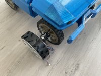
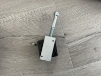
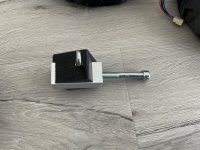
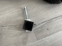
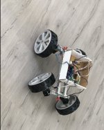
„EVE“ - by Fürst Ruprecht ( I only do four-wheel drive )

Fürst Ruprecht

Well-known member
Hier geht es um einen Mähroboter mit Allrad - Antrieb und Allrad - Lenkung.

Die Lenkung soll geschwindigkeitsabhängig die hinteren Räder ansteuern:
Langsam:
/—/ Vorn
\—\ Hinten
Schnell:
/—/ Vorn
/—/ Hinten

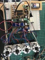
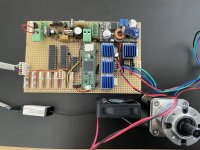
Aktuelle Basis :
Teensy4.1,
Nema 17 Stepper mit 19.1:1 Getriebe,
TMC2208 Stepper Driver,
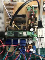
Platine DIY.
Port - Erweiterung mit MCP23S17 (16bit I/O-Expander) und MCP3008 (8-Channel 10-bit A/D-Converter).
Spannungsmessung mit Ina139 (analog) an MCP3008.
Software ist eine Modifikation auf Basis von der hier verwendeten Teensy-AzuritBer Version.
11D8C7CA-2C66-4B1A-940C-22C6D7F309CD.jpeg

Hardware:
Mein erstes Problem: Ich nutze bei der Spannungsversorgung an Stelle des IRF9540N ( Mosfet P-Kanal) den IRLIZ44N ( Mosfet N-Kanal). Dadurch kehrt sich die Polarität bei der Ansteuerung um. Problem: der Spannungsabfall liegt bei ca. 2V (leitend). Ist das normal ?

Software:
Der Entfall der Odometrie führt zu umfangreichen Änderungen in der Software. Solange der Steppermotor dreht, kennt man die Radbewegung und muß sie nicht ermitteln, daher wird das Zählen der Ticks am Rad durch eine Berechnung über die gemachten Steps ersetzt. Die Motoren werden jedoch nicht per Steps angesteuert, sondern durch die Vorgabe einer Drehzahl, die vom Stepper-Driver intern in Steps gewandelt wird.
Ursprünglich wollte ich die Sonar Sensoren über den MCP23S17 ansteuern. Dazu sollte das Echosignal einen Interrupt auslösen und dann der Teensy über die Zeitdifferenz zwischen Tricker und Interrupt die Distanz berechnen. Das hat bis jetzt leider nicht funktioniert, die Zeiten sind völlig unbrauchbar.

Aktueller Stand:
Platine funktioniert soweit. Motoren sind per RC-Fernbedienung steuerbar. Programm ist (bis auf I/O-Expander) grob angepaßt.

Gruß Fürst Ruprecht
 
Die PCB sieht interessant aus. Beim Spannungsabfall bin ich mir leider nicht sicher, ob der auch bei der PowerPCB so ist. Habe ich nicht nachgemessen.
Warum hast du den IRLIZ44N genommen, gab es da einen speziellen Grund, oder hattest du den einfach da?
 
Do you have a schematics of the PCB.

Why MCP23S17 (SPI) instead of MCP23017 (I2C version using only 2 pins) ?
For sonar and all high speed management like perimeter and PWM it's better to directly use the teensy IO.
For bumper ,button, led , rain sensor etc the MCP23017 is certainly OK.

I have here some MCP23017 for testing with teensy and 5V IN OUT management but need more test before adding it on the next main PCB.
 
Die PCB sieht interessant aus. Beim Spannungsabfall bin ich mir leider nicht sicher, ob der auch bei der PowerPCB so ist. Habe ich nicht nachgemessen.
Warum hast du den IRLIZ44N genommen, gab es da einen speziellen Grund, oder hattest du den einfach da?
Hatte ich da, war billiger und kann direkt laden beim Kontaktieren mit dem Ladegerät. Aber der Spannungsabfall ist zu hoch, das kann so nicht bleiben. Ich bin leider nicht so vertraut mit den Mosfets. Die Ansteuerung ist auf den ersten Blick in Ordnung (nachgemessen).
 
Bernard,
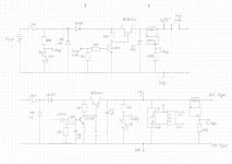
I have handwritten documents. I will post them here. I took the S-Type for speed, thinking I could dock sonar directly. However, I still have an error with the interrupt task. I just read today, that I have to insert asm (...) so that the interrupt doesn't run twice. That was the problem so far. I will move the two signals for battery and charge from the Teensy to the MCP23S17, then enough pins will be free on the Teensy.
 
Stand 21.03.2022
TeensyStepper1.jpg
Teensy-Stepper Platine : Part1 - Powersupply
Platine funktioniert soweit.
Problem: am IRLIZ44N fallen 2V Spannung ab.
Lösung1: Wechsel auf p-Kanal Mosfet
Lösung2: Gate über 4K7 an Eingang Diode SB1240 (höhere Gate-Spannung)

Software:
MC3008 ADC-Converter - OK
MCP23S17 I/O-Expander - OK
MMC5883MA - Compass (3,3V) - OK
ESP32 mit pfod - OK
RC-Remote - OK
TMC2208 Stepper Driver - OK

Sonar - NOK
Perimeter -NOK

Soweit läuft auf dem Tisch jetzt ein STARK angepaßtes azuritBer-Stepper. Leider fehlt noch das Chassis.
Weitere Unterlagen stelle ich Euch ein.

Gruß Fürst Ruprecht
 
Problem: am IRLIZ44N fallen 2V Spannung ab.
Why you don't use the PowerPCB ,it can manage battery and 5 motor sense using INA226, or simply use IRF9540N like on Teensy Power PCB.

MC3008 ADC-Converter - OK
MCP23S17 I/O-Expander - OK
Very cool ,maybe you can share your teensy code management for this module.

MMC5883MA - Compass (3,3V) - OK
What about accuracy inside a full chassis (All my test on HMC and QMC5883 always fail with +-10 degres)
 
What about accuracy inside a full chassis (All my test on HMC and QMC5883 always fail with +-10 degres)
Yes that is a problem. The fluctuations are around 5 degrees. This means that the steering is constantly working. I still had an MMC5883MA in stock and no experience with other modules. If it goes better, I'll swap the component.
Why you don't use the PowerPCB ,it can manage battery and 5 motor sense using INA226, or simply use IRF9540N like on Teensy Power PCB.
I figured I'll have to make a PCB anyway, so I'm putting the power components as well. Ina 226 are a simple but large and expensive solution. Why didn't you just make a circuit board for stepper motors, ha, ha, ha.
Very cool ,maybe you can share your teensy code management for this module.
I'm afraid I was brutal with your code. But of course I'll post my code. The right setting of the TMC2208 took a lot of trial and error.
I merged mower and robot and deleted a lot of code that I won't be using. Maybe you can reduce some complexity, that would help to understand the code better.
 
for stepper motors, ha, ha, ha.
I use already stepper motor in automation and yes it's something easy to use and very strong at low cost, but i am not sure about the power consumption on a battery powered platform .
You can help a lot with a long time feedback.

Ina 226 are a simple but large and expensive
Yes maybe 2 * INA3221 can do the stuff .It's limit to 26V but i use 2 inside WIFI senders since 2 Years at 29.4 V and never issue !!!

for IMU MPU6050 locate inside GY-521 GY-87 or GY-88 are really more accurate than a magnetometer (+/- 2 degres ,but drift over time)

Maybe you can reduce some complexity
YES it's sure, code was based on AZURIT and many change since the beginning but no problem if you tell me were ?

I merged mower and robot and deleted a lot of code
Mower.cpp and mower.h are file containing the main electrical description of the mower and factory setting .
They are different for each platform and it's the reason why they are separate from robot.cpp.

For example i work actualy on 2 teensy platform (RL2000 and MI-632) for each platform i use different mower file (different pin mapping for example) but all the other code is the same , so i simply rename my mowerRl2000.xxx to mower.cpp or mower632.xxx and i can compile without issue for each platform.
A mowerT800.xxx can be create for T800 platform for example and when a new version of the APP is build ,you can compile without always check if you forget something on pin mapping for example.

In all case GOOD LUCK to understand my code :ROFLMAO: :ROFLMAO: :ROFLMAO: :ROFLMAO: :ROFLMAO: but no problem to help to explain.
 
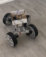
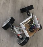
Prototyp fährt ! Video folgt.
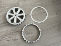
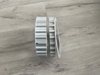
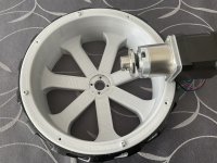
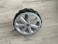
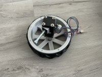
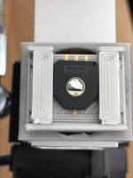
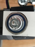
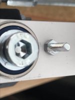
Rad, Reifen, Achse:
Reifen TPU, Reifen und Felge in 4cm Breite + 2cm Verbreiterung (optional , for showcars only!)
A21D55DA-A939-49D5-8D05-9419D525BC7F.jpegEFDEB083-E1B6-41DA-B803-0E9687985094.jpegF5846E1F-657A-4757-A646-5D1F1D17E74F.jpegC2ECF8BD-EA7A-4880-9B37-2277C6B7F22B.jpeg862EBFA2-1C13-49CA-AB6F-13C833F06099.jpeg3C7FB251-8647-48CC-8A28-1A9892D23C98.jpegE6117279-F26E-41C2-B27E-00CFC5CAEFDC.jpeg55065087-7EFB-4723-B49C-D68444996A06.jpegB3B6A6F4-939A-45FD-8BEA-A5323F6F8D5E.jpeg
 
Back
Top