PowerPCB Discussion

Sascha

Administrator
Staff member
Since the PowerPCB doesn't make me happy at the moment, because Q4 always breaks, I'm looking for alternatives.
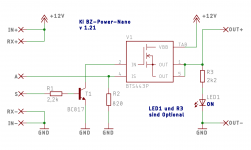
In the process, I became aware of the BTS443P Smart Highside Power Switch. Does anyone happen to have one lying around and could try out the circuit? But it's missing the power button, maybe you can make it between +12V and Out+?
The 12V can be ignored, the BTS can handle 36V 24A.
 

Attachments

  • ki_bz-power-nano-schaltbild.png
    ki_bz-power-nano-schaltbild.png
    136.9 KB · Views: 22
Habe mir den Baustein mal angesehen. Finde ihn ganz interessant. Gibt auch Rückschluss über den Laststrom.
Dennoch ist die Frage: Warum funktioniert die aktuelle Schaltung nicht.
 
Why did you say that Power PCB don't work ??
For me Only issue is :
At the end of the charging Battery is used to power the PCB , so after 3 days in the station charging start again.
It's can easily be solved by software (simply power off everything if no timer is used.
 
I did not write that it does not work, but that it does not work for me. But it can also simply be due to the quality of the components, the charging circuit works as it should.
 
@Bernard can you tell me how much space you need for the heat sink on Q4?
 

Attachments

  • charge_pcb.jpg
    charge_pcb.jpg
    93.6 KB · Views: 16
Any change requests?
The labelling should be sufficient for the INA's, I think.
 

Attachments

  • charge_pcb.pdf
    67.9 KB · Views: 2
  • charge_pcb_1.jpg
    charge_pcb_1.jpg
    125 KB · Views: 13
The 24V go out there for step down etc.
The emergency switch is labeled as power switch. Maybe I should change the labelling?
I didn't even look at how it was labelled before.
 
Back
Top